The thermal efficiency in terms of the compressor pressure ratio (PR = p2/p1), which is the parameter commonly used:
In general, increasing the pressure ratio is the most direct way to increase the overall thermal efficiency of a Brayton cycle.
In 1872, an American engineer, George Bailey Brayton, advanced the study of heat engines by patenting a constant pressure internal combustion engine, initially using vaporized gas but later using liquid fuels such as kerosene. This heat engine is known as “Brayton’s Ready Motor”. The original Brayton engine used a piston compressor and piston expander instead of a gas turbine and gas compressor.
Today, modern gas turbine engines and airbreathing jet engines are also constant-pressure heat engines. Therefore we describe their thermodynamics by the Brayton cycle. In general, the Brayton cycle describes the workings of a constant-pressure heat engine.
It is one of the most common thermodynamic cycles found in gas turbine power plants or airplanes. In contrast to the Carnot cycle, the Brayton cycle does not execute isothermal processes because these must be performed very slowly. In an ideal Brayton cycle, the system executing the cycle undergoes a series of four processes: two isentropic (reversible adiabatic) processes alternated with two isobaric processes.
Since Carnot’s principle states that no engine can be more efficient than a reversible engine (a Carnot heat engine) operating between the same high temperature and low-temperature reservoirs, a gas turbine based on the Brayton cycle must have lower efficiency than the Carnot efficiency.
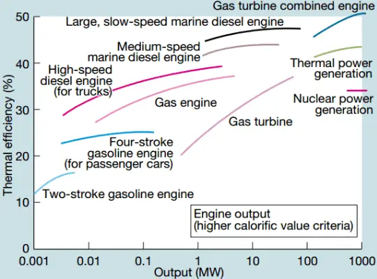
A large single-cycle gas turbine typically produces 300 megawatts of electric power and has 35–40% thermal efficiency. Modern Combined Cycle Gas Turbine (CCGT) plants, in which the thermodynamic cycle consists of two power plant cycles (e.g.,, the Brayton cycle and the Rankine cycle), can achieve a thermal efficiency of around 55%.
Types of Gas Turbines
In general, heat engines and also gas turbines are categorized according to a combustion location as:
- Turbines with internal combustion. Most gas turbines are internal combustion engines. In these turbines, the high temperature is achieved by burning the fuel-air mixture in the combustion chamber.
- Turbines with external combustion. A heat exchanger is usually used in these turbines, and only a clean medium with no combustion products travels through the power turbine. Since the turbine blades are not subjected to combustion products, much lower quality (and therefore cheaper) fuels can be used. These turbines usually have lower thermal efficiency than turbines with internal combustion.
Types of Brayton Cycle
Open Brayton Cycle (keywords)
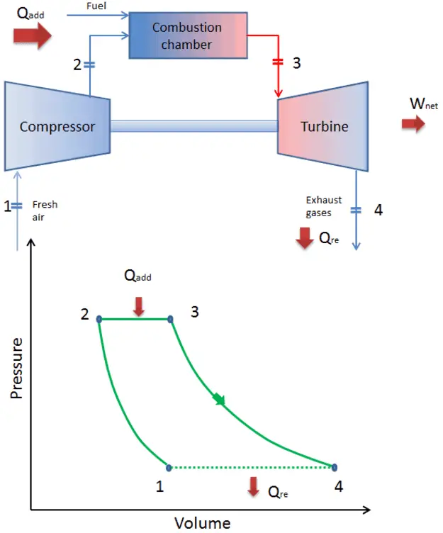
Since most gas turbines are based on the Brayton cycle with internal combustion (e.g.,, jet engines), they are based on the open Brayton cycle. In this cycle, air from the ambient atmosphere is compressed to the compressor’s higher pressure and temperature. In the combustion chamber, the air is heated further by burning the fuel-air mixture in the airflow. Combustion products and gases expand in the turbine either to near atmospheric pressure (engines producing mechanical energy or electrical energy) or to a pressure required by the jet engines. The open Brayton cycle means that the gases are discharged directly into the atmosphere.
Closed Brayton Cycle
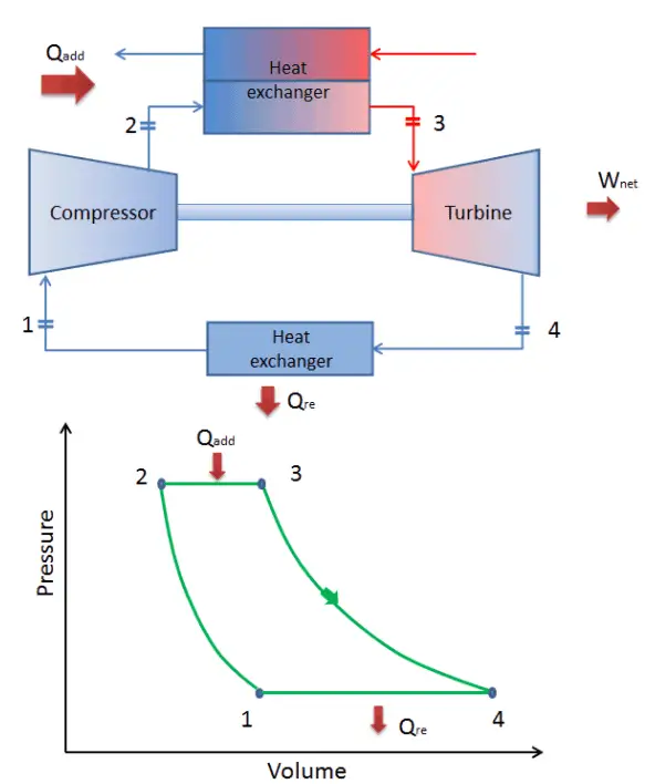
In a closed Brayton cycle, the working medium (e.g.,, helium) recirculates in the loop, and the gas expelled from the turbine is reintroduced into the compressor. A heat exchanger (external combustion) is usually used in these turbines, and only a clean medium with no combustion products travels through the power turbine. The closed Brayton cycle is used, for example, in closed-cycle gas turbines and high-temperature gas-cooled reactors.
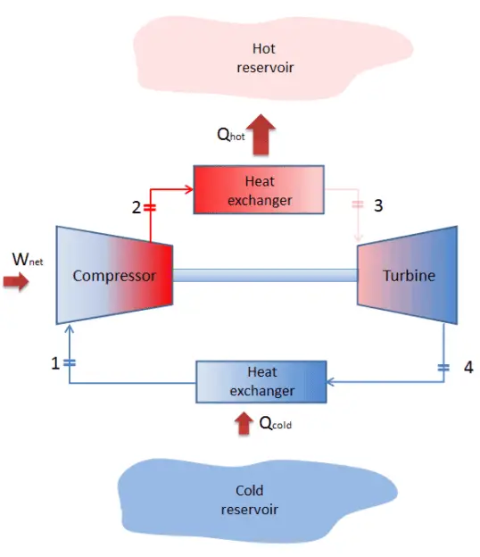
Reverse Brayton Cycle – Brayton Refrigeration Cycle
A Brayton cycle that is driven in the reverse direction is known as the reverse Brayton cycle. Its purpose is to move heat from the colder to the hotter body rather than produce work. In compliance with the second law of thermodynamics, Heat cannot spontaneously flow from cold system to hot system without external work being performed on the system. Heat can flow from colder to the hotter body, but only when forced by external work. This is exactly what refrigerators and heat pumps accomplish. These are driven by electric motors requiring work from their surroundings to operate. One of the possible cycles is a reverse Brayton cycle, which is similar to the ordinary Brayton cycle, but it is driven in reverse via a network input. This cycle is also known as the gas refrigeration cycle or the Bell Coleman cycle. This cycle is widely used in jet aircraft for air conditioning systems using air from the engine compressors. It is also widely used in the LNG industry. The largest reverse Brayton cycle is for subcooling LNG using 86 MW of power from a gas turbine-driven compressor and nitrogen refrigerant.
Brayton Cycle – Processes
In a closed ideal Brayton cycle, the system executing the cycle undergoes a series of four processes: two isentropic (reversible adiabatic) processes alternated with two isobaric processes:
-

closed Brayton cycle Isentropic compression (compression in a compressor) – The working gas (e.g.,, helium) is compressed adiabatically from state 1 to state 2 by the compressor (usually an axial-flow compressor). The surroundings work on the gas, increasing its internal energy (temperature) and compressing it (increasing its pressure). On the other hand, the entropy remains unchanged. The work required for the compressor is given by WC = H2 – H1.
- Isobaric heat addition (in a heat exchanger) – In this phase (between state 2 and state 3), there is a constant-pressure heat transfer to the gas from an external source since the chamber is open to flow in and out. In an open ideal Brayton cycle, the compressed air runs through a combustion chamber, burning fuel, and air or another medium is heated (2 → 3). It is a constant-pressure process since the chamber is open to flow in and out. The net heat added is given by Qadd = H3 – H2
- Isentropic expansion (expansion in a turbine) – The compressed and heated gas expands adiabatically from state 3 to state 4 in a turbine. The gas works on the surroundings (blades of the turbine) and loses an amount of internal energy equal to the work that leaves the system. The work done by the turbine is given by WT = H4 – H3. Again the entropy remains unchanged.
- Isobaric heat rejection (in a heat exchanger) – In this phase, the cycle completes by a constant-pressure process in which heat is rejected from the gas. The working gas temperature drops from point 4 to point 1. The net heat rejected is given by Qre = H4 – H1
During a Brayton cycle, work is done on the gas by the compressor between states 1 and 2 (isentropic compression). Work is done by the gas in the turbine between stages 3 and 4 (isentropic expansion). The difference between the work done by the gas and the work done on the gas is the network produced by the cycle, and it corresponds to the area enclosed by the cycle curve (in the pV diagram).
As can be seen, it is convenient to use enthalpy or specific enthalpy and express the first law in terms of enthalpy in the analysis of this thermodynamic cycle. This form of the law simplifies the description of energy transfer. At constant pressure, the enthalpy change equals the energy transferred from the environment through heating:
Isobaric process (Vdp = 0):
dH = dQ → Q = H2 – H1
At constant entropy, i.e., in isentropic process, the enthalpy change equals the flow process work done on or by the system:
Isentropic process (dQ = 0):
dH = Vdp → W = H2 – H1
See also: Why power engineers use enthalpy? Answer: dH = dQ + Vdp
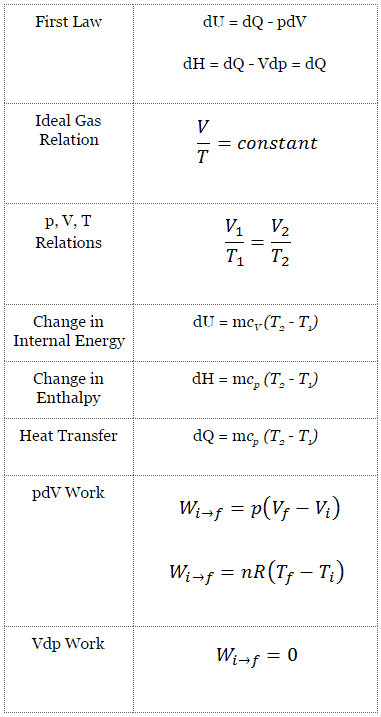
Isentropic Process
An isentropic process is a thermodynamic process in which the entropy of the fluid or gas remains constant. It means the isentropic process is a special case of an adiabatic process in which there is no transfer of heat or matter. It is a reversible adiabatic process. The assumption of no heat transfer is very important since we can use the adiabatic approximation only in very rapid processes.
Isentropic Process and the First Law
For a closed system, we can write the first law of thermodynamics in terms of enthalpy:
dH = dQ + Vdp
or
dH = TdS + Vdp
Isentropic process (dQ = 0):
dH = Vdp → W = H2 – H1 → H2 – H1 = Cp (T2 – T1) (for ideal gas)
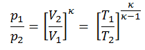
Isentropic Process of the Ideal Gas
The isentropic process (a special case of the adiabatic process) can be expressed with the ideal gas law as:
pVκ = constant
or
p1V1κ = p2V2κ
in which κ = cp/cv is the ratio of the specific heats (or heat capacities) for the gas. One for constant pressure (cp) and one for constant volume (cv). Note that, this ratio κ = cp/cv is a factor in determining the speed of sound in a gas and other adiabatic processes.
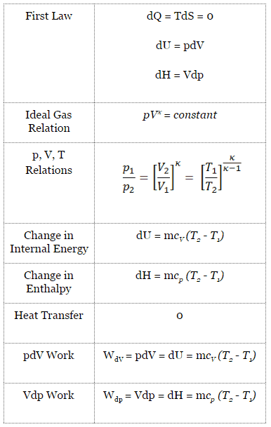
Isobaric Process
An isobaric process is a thermodynamic process in which the system’s pressure remains constant (p = const). The heat transfer into or out of the system does work and changes the system’s internal energy.
Since there are changes in internal energy (dU) and changes in system volume (∆V), engineers often use the enthalpy of the system, which is defined as:
H = U + pV
Isobaric Process and the First Law
The classical form of the first law of thermodynamics is the following equation:
dU = dQ – dW
In this equation, dW is equal to dW = pdV and is known as the boundary work. In an isobaric process and the ideal gas, part of the heat added to the system will be used to do work, and part of the heat added will increase the internal energy (increase the temperature). Therefore it is convenient to use enthalpy instead of internal energy.
Isobaric process (Vdp = 0):
dH = dQ → Q = H2– H1
At constant entropy, i.e., in the isentropic process, the enthalpy change equals the flow process work done on or by the system.
Isobaric Process of the Ideal Gas
The isobaric process can be expressed with the ideal gas law as:
or

On a p-V diagram, the process occurs along a horizontal line (called an isobar) with the equation p = constant.
See also: Charles’s Law
Brayton Cycle – pV, Ts diagram
The Brayton cycle is often plotted on a pressure-volume diagram (pV diagram) and a temperature-entropy diagram (Ts diagram).
When plotted on a pressure-volume diagram, the isobaric processes follow the isobaric lines for the gas (the horizontal lines), adiabatic processes move between these horizontal lines, and the area bounded by the complete cycle path represents the total work that can be done during one cycle.
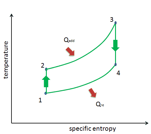
The temperature-entropy diagram (Ts diagram) in which the thermodynamic state is specified by a point on a graph with specific entropy (s) as the horizontal axis and absolute temperature (T) as the vertical axis. Ts diagrams are a useful and common tool, particularly because it helps to visualize the heat transfer during a process. For reversible (ideal) processes, the area under the T-s curve of a process is the heat transferred to the system during that process.
Thermal Efficiency of Brayton Cycle
In general, the thermal efficiency, ηth, of any heat engine is defined as the ratio of the work it does, W, to the heat input at the high temperature, QH.
The thermal efficiency, ηth, represents the fraction of heat, QH, converted to work. Since energy is conserved according to the first law of thermodynamics and energy cannot be converted to work completely, the heat input, QH, must equal the work done, W, plus the heat that must be dissipated as waste heat QC into the environment. Therefore we can rewrite the formula for thermal efficiency as:

This is a very useful formula, but we express the thermal efficiency using the first law in terms of enthalpy.
To calculate the thermal efficiency of the Brayton cycle (single compressor and single turbine), engineers use the first law of thermodynamics in terms of enthalpy rather than internal energy.
The first law in terms of enthalpy is:
dH = dQ + Vdp
In this equation, the term Vdp is a flow process work. This work, Vdp, is used for open flow systems like a turbine or a pump in which there is a “dp”, i.e., change in pressure. There are no changes in the control volume. As can be seen, this form of the law simplifies the description of energy transfer.
There are expressions in terms of more familiar variables such as temperature and pressure:
dH = CpdT + V(1-αT)dp
Where Cp is the heat capacity at constant pressure and α is the (cubic) thermal expansion coefficient. For ideal gas αT = 1 and therefore:
dH = CpdT
At constant pressure, the enthalpy change equals the energy transferred from the environment through heating:
Isobaric process (Vdp = 0):
dH = dQ → Q = H3 – H2 → H3 – H2 = Cp (T3 – T2)
At constant entropy, i.e., in isentropic process, the enthalpy change equals the flow process work done on or by the system:
Isentropic process (dQ = 0):
dH = Vdp → W = H4 – H3 → H4 – H3 = Cp (T4 – T3)
The enthalpy can be made into an intensive or specific variable by dividing by the mass. Engineers use the specific enthalpy in thermodynamic analysis more than the enthalpy itself.
Now, let assume the ideal Brayton cycle that describes the workings of a constant pressure heat engine. Modern gas turbine engines and airbreathing jet engines also follow the Brayton cycle. This cycle consist of four thermodynamic processes:
-
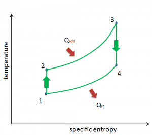
Brayton Cycle – Ts diagram Isentropic compression – ambient air is drawn into the compressor, pressurized (1 → 2). The work required for the compressor is given by WC = H2 – H1.
- Isobaric heat addition – the compressed air then runs through a combustion chamber, burning fuel, and air or another medium is heated (2 → 3). It is a constant-pressure process since the chamber is open to flow in and out. The net heat added is given by Qadd = H3 – H2
- Isentropic expansion – the heated, pressurized air then expands on a turbine, gives up its energy. The work done by the turbine is given by WT = H4 – H3
- Isobaric heat rejection – the residual heat must be rejected to close the cycle. The net heat rejected is given by Qre = H4 – H1
As can be seen, we can fully describe and calculate such cycles (similarly for Rankine cycle) using enthalpies.
The thermal efficiency of such a simple Brayton cycle for ideal gas and in terms of specific enthalpies can now be expressed in terms of the temperatures:

where
- WT the work done by the gas in the turbine
- WC the work done on the gas in the compressor
- cp is the heat capacity ratio
Pressure Ratio – Brayton Cycle – Gas Turbine
The thermal efficiency in terms of the compressor pressure ratio (PR = p2/p1), which is the parameter commonly used:
 In general, increasing the pressure ratio is the most direct way to increase the overall thermal efficiency of a Brayton cycle because the cycle approaches the Carnot cycle.
According to Carnot’s principle, higher efficiencies can be attained by increasing the temperature of the gas.
But there are also limits on the pressure ratios that can be used in the cycle. The highest temperature in the cycle occurs at the end of the combustion process, and it is limited by the maximum temperature that the turbine blades can withstand. As usual, metallurgical considerations (about 1700 K) place upper limits on thermal efficiency.
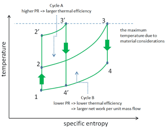
Consider the effect of compressor pressure ratio on thermal efficiency when the turbine inlet temperature is restricted to the maximum allowable temperature. There are two Ts diagrams of Brayton cycles having the same turbine inlet temperature but different compressor pressure ratios on the picture. As can be seen for a fixed-turbine inlet temperature, the network output per cycle (Wnet = WT – WC) decreases with the pressure ratio (Cycle A). But the Cycle A has greater efficiency.
On the other hand, Cycle B has a larger network output per cycle (enclosed area in the diagram) and thus the greater network developed per unit of mass flow. The work produced by the cycle times a mass flow rate through the cycle is equal to the power output produced by the gas turbine.
Therefore with less work output per cycle (Cycle A), a larger mass flow rate (thus a larger system) is needed to maintain the same power output, which may not be economical. This is the key consideration in the gas turbine design since here. Engineers must balance thermal efficiency and compactness. In most common designs, the pressure ratio of a gas turbine ranges from about 11 to 16.
Thermal Efficiency Improvement – Brayton Cycle
There are several methods, how can be the thermal efficiency of the Brayton cycle improved. Assuming that the maximum temperature is limited by metallurgical consideration, these methods are:
As was discussed, increasing the pressure ratio increases the compressor discharge temperature. Since the turbine inlet temperature is limited by the maximum temperature that the turbine blades can withstand, the pressure ratio influences the heat amount added to the flow. Moreover, with an increase in the pressure ratio, the diameter of the compressor blades becomes progressively smaller in higher pressure stages of the compressor. Because the gap between the blades and the engine casing increases in size as a percentage of the compressor blade height as the blades get smaller in diameter. A greater percentage of the compressed air can leak back past the blades in higher pressure stages. This causes a leak back, and as a result, it decreases the isentropic compressor efficiency (will be discussed later). Finally, from the formula for the thermal efficiency in terms of pressure ratio can be seen, there is a smaller gain as the pressure ratio increases (due to the exponent).
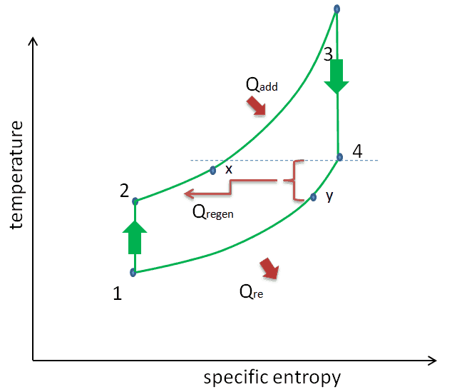
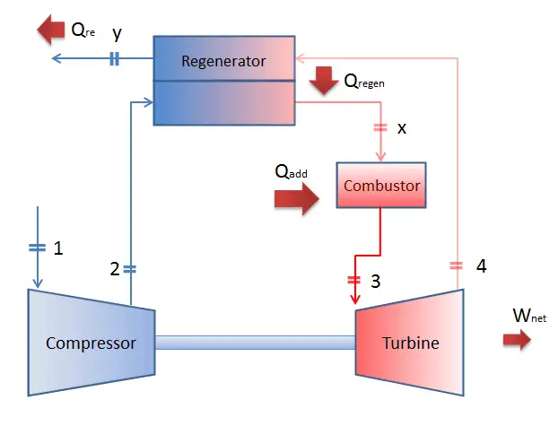
Significant increases in the thermal efficiency of gas turbine power plants can be achieved by reducing the amount of fuel that must be burned in the combustion chamber. This can be done by transferring heat from the turbine exhaust gas, which is normally well above the ambient temperature, to the compressor discharge airflow, heat regeneration. Especially at a low or moderate pressure ratio, there is a high-temperature increase in the combustion chamber. The turbine exhaust gas might still contain a significant amount of heat at a higher temperature than the compressor outlet gas (after the last compression stage but before the combustor). For this purpose, a heat exchanger called a regenerator is used. Sometimes engineers use the term economizer that is a heat exchanger intended to reduce energy consumption, especially in preheating a fluid.
This heat regenerator allows the air exiting the compressor to be preheated before entering the combustion chamber, reducing the amount of fuel that must be burned in the combustor. This form of heat recycling is only possible if the gas turbine is run with a low-pressure ratio.
As stated, the temperature difference between the turbine and compressor outlets is crucial and determines the amount of heat that can be recovered. In case of negative difference (i.e., T2 > T4), heat regeneration is not possible. There are two main ways, how to change this difference:
- to increase the turbine outlet temperature (T4) through reheat of the flow during the expansion phase (i.e., use of a multi-stage turbine with a reheat combustor or with a reheater)
- to decrease the compressor outlet temperature (T2) through inter-cooling of the flow during the compression phase (i.e., use of a multi-stage compressor with an intercooler)
Therefore reheat, and inter-cooling are complementary with heat regeneration. By themselves, they would not necessarily increase the thermal efficiency. However, a significant increase in thermal efficiency can be achieved when inter-cooling or reheat is used in conjunction with heat regeneration.
It must be noted, transferring heat from the turbine outlet to the compressor inlet would reduce efficiency, as hotter inlet air means more volume, thus more work for the compressor. Engineers must also consider pressure losses generated by the heat exchanger that slightly reduce the power of the gas turbine.
Regeneration vs. Recuperation of Heat
In general, the heat exchangers used in regeneration may be classified as either regenerators or recuperators.
- A regenerator is a heat exchanger where heat from the hot fluid is intermittently stored in a thermal storage medium before it is transferred to the cold fluid. It has a single flow path in which the hot and cold fluids alternately pass through.
- A recuperator is a heat exchanger with separate flow paths for each fluid along its passages, and heat is transferred through the separating walls. Recuperators (e.g.,, economizers) are often used in power engineering to increase the overall efficiency of thermodynamic cycles, for example, in a gas turbine engine. The recuperator transfers some of the waste heat in the exhaust to the compressed air, thus preheating it before entering the combustion chamber. Many recuperators are designed as counterflow heat exchangers.

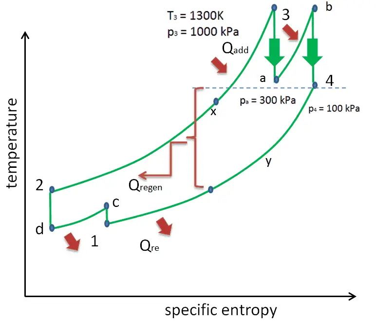
As discussed, the maximum temperature is limited by metallurgical consideration. Still, to deliver more heat at a temperature close to the cycle’s peak, the gas can be reheated in a reheater. This involves splitting the turbine, i.e., using a multi-stage turbine with a reheat combustor or a reheater. The turbine’s high and low-pressure stages may be on the same shaft to drive a common generator, but they will have separate cases. With a reheater, the flow is extracted after a partial expansion (point a), run back through the heat exchanger to heat it back up to the peak temperature (point b), and then passed to the lower pressure stage of the turbine. The expansion is then completed in this stage from point b to point 4.
With this arrangement, the network per unit of mass flow can be increased. Despite the increase in network with reheat, the cycle thermal efficiency would not necessarily increase because a greater total heat addition would be required. On the other hand, the temperature at the exit of the turbine (low-pressure stage) is higher with reheat than without reheat, so there is the potential for heat regeneration. Therefore reheat, and regeneration is complementary. They are usually used together to increase the thermal efficiency of a gas turbine.

Significant increases in the thermal efficiency of gas turbine power plants can also be achieved through inter-cooling. Inter-cooling can be applied between compressor stages to reduce compression work, WC, hence increasing the overall power of the gas turbine.
For this purpose, a heat exchanger known as an intercooler is usually used between stages of a multi-stage compression process. In general, intercoolers are heat exchangers used in many applications, including air compressors, air conditioners, refrigerators, and gas turbines. Intercoolers are also widely known in automotive use as turbochargers or superchargers, but here they increase intake air charge density, hence the power of an engine.
In a gas turbine power plant, thermal efficiency is highly important, and inter-cooling with heat regeneration is widely used. This involves splitting the compressor, i.e., using a multi-stage compressor with an intercooler or intercooler. The compressor’s high pressure and low-pressure stages may be on the same shaft, even with a turbine or a generator, but it is not a rule. With an intercooler, the flow is extracted after a partial compression (point c), run through the heat exchanger (intercooler) to cool it to the ambient temperature (point d), and then passed to the high stage of the compressor. The compression is then completed in the second compressor from point d to point 2.
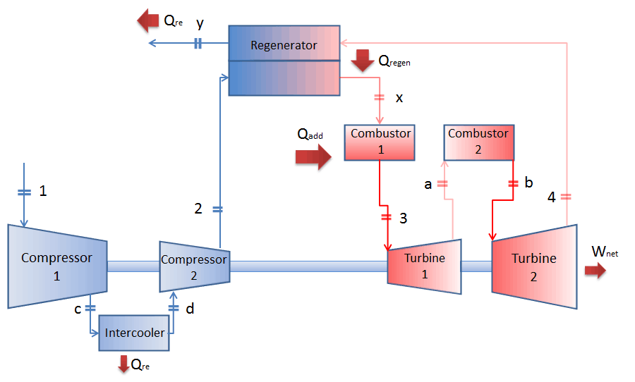
With this arrangement, the network per unit of mass flow (↑Wnet = WT – ↓WC) can be increased by reducing the compression work (↓WC). Despite the increase in network with inter-cooling, the cycle thermal efficiency would not necessarily increase because the temperature of the air entering the combustor would be reduced, and a greater total heat addition would be required to achieve the desired turbine inlet temperature. On the other hand, the temperature at the exit of the compressor (high-pressure stage) is lower with inter-cooling than without inter-cooling, so there is the potential for heat regeneration (Qregen increases). Note that the heat regeneration requires a lower compressor outlet temperature than the turbine outlet temperature (simply due to the 2nd law). This temperature difference determines the amount of heat available for heat regeneration.
Therefore reheat, and inter-cooling are complementary with heat regeneration. By themselves, they would not necessarily increase the thermal efficiency. However, a significant increase in thermal efficiency can be achieved when inter-cooling or reheat is used in conjunction with heat regeneration.
Some large compressors with higher pressure ratios have several stages of compression with inter-cooling between stages. Engineers must also take into consideration pressure losses generated by all heat exchangers that slightly increase compression work. The certain gas turbine design (the number of intercoolers, reheaters, and regenerators) is an engineering problem and depends on the certain purpose of the gas turbine.
Reheat, Intercooling and Regeneration in Brayton Cycle
As was discussed, reheat and inter-cooling are complementary to heat regeneration. By themselves, they would not necessarily increase the thermal efficiency, however, when inter-cooling or reheat is used in conjunction with heat regeneration, a significant increase in thermal efficiency can be achieved, and the network output is also increased. This requires a gas turbine with two stages of compression and two turbine stages.

The second Ericsson cycle is similar to the Brayton cycle but uses external heat and incorporates the multiple uses of an inter-cooling and reheat. It is like a Brayton cycle with an infinite number of reheat and intercooler stages in the cycle. Compared to the Brayton cycle, which uses adiabatic compression and expansion, an ideal Ericsson cycle consists of isothermal compression and expansion processes, combined with isobaric heat regeneration between them. Applying inter-cooling, heat regeneration, and sequential combustion significantly increase the thermal efficiency of a turbine. The thermal efficiency of the ideal Ericsson cycle equals the Carnot efficiency.
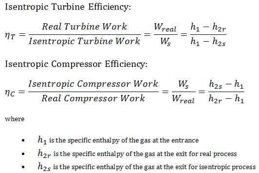
Isentropic Efficiency – Turbine, Compressor
Most steady-flow devices (turbines, compressors, nozzles) operate under adiabatic conditions, but they are not truly isentropic but are rather idealized as isentropic for calculation purposes. We define parameters ηT, ηC, ηN, as a ratio of real work done by the device to work by the device when operated under isentropic conditions (in case of a turbine). This ratio is known as the Isentropic Turbine/Compressor/Nozzle Efficiency.
See also: Irreversibility of Natural Processes
These parameters describe how efficiently a turbine, compressor, or nozzle approximates a corresponding isentropic device. This parameter reduces the overall efficiency and work output. For turbines, the value of ηT is typically 0.7 to 0.9 (70–90%).

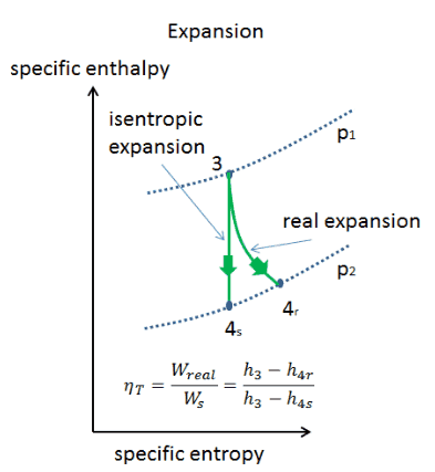
Assume an isentropic expansion of helium (3 → 4) in a gas turbine. In these turbines, the high-pressure stage receives gas (point 3 at the figure; p3 = 6.7 MPa; T3 = 1190 K (917°C)) from a heat exchanger and exhausts it to another heat exchanger, where the outlet pressure is p4 = 2.78 MPa (point 4). The temperature (for the isentropic process) of the gas at the exit of the turbine is T4s = 839 K (566°C).
Calculate the work done by this turbine and calculate the real temperature at the exit of the turbine when the isentropic turbine efficiency is ηT = 0.91 (91%).
Solution:
From the first law of thermodynamics, the work done by the turbine in an isentropic process can be calculated from:
WT = h3 – h4s → WTs = cp (T3 – T4s)
From Ideal Gas Law we know, that the molar specific heat of a monatomic ideal gas is:
Cv = 3/2R = 12.5 J/mol K and Cp = Cv + R = 5/2R = 20.8 J/mol K
We transfer the specific heat capacities into units of J/kg K via:
cp = Cp . 1/M (molar weight of helium) = 20.8 x 4.10-3 = 5200 J/kg K
The work done by gas turbine in isentropic process is then:
WT,s = cp (T3 – T4s) = 5200 x (1190 – 839) = 1.825 MJ/kg
The real work done by gas turbine in adiabatic process is then:
WT,real = cp (T3 – T4s) . ηT = 5200 x (1190 – 839) x 0.91 = 1.661 MJ/kg
Brayton Cycle – Problem with Solution
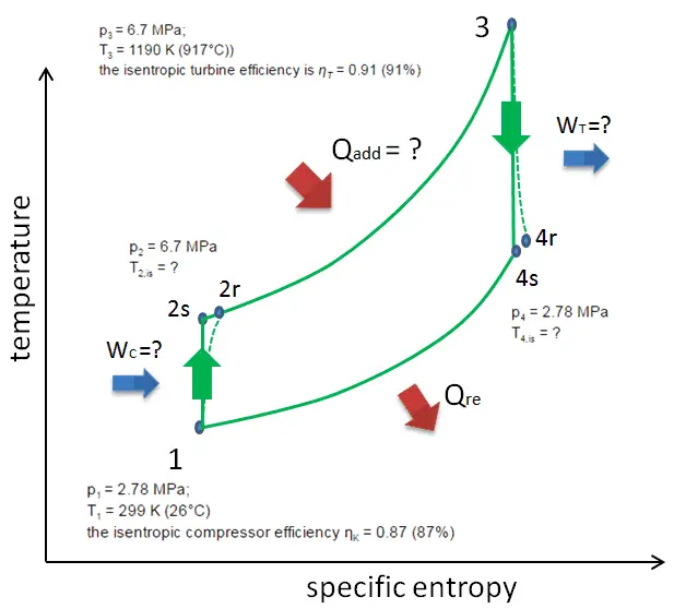
 Let assume the closed Brayton cycle, one of the most common thermodynamic cycles found in modern gas turbine engines. In this case, assume a helium gas turbine with a single compressor and single turbine arrangement. One of the key parameters of such engines is the maximum turbine inlet temperature and the compressor pressure ratio (PR = p2/p1), which determines the thermal efficiency of such engines.
In this turbine, the high-pressure stage receives gas (point 3 at the figure) from a heat exchanger:
- p3 = 6.7 MPa;
- T3 = 1190 K (917°C))
- the isentropic turbine efficiency is ηT = 0.91 (91%)
and exhaust it to another heat exchanger, where the outlet pressure is (point 4):
- p4 = 2.78 MPa
- T4,is = ?
Thus the compressor pressure ratio is equal to PR = 2.41. Moreover, we know that the compressor receives gas (point 1) at the figure:
- p1 = 2.78 MPa;
- T1 = 299 K (26°C)
- the isentropic compressor efficiency ηK = 0.87 (87%).
The heat capacity ratio for helium is equal to =cp/cv=1.66
 Calculate:
- the heat added by the heat exchanger (between 2 → 3)
- the compressor outlet temperature of the gas (T2,is)
- the real work done on this compressor when the isentropic compressor efficiency is ηK = 0.87 (87%)
- the turbine outlet temperature of the gas (T4,is)
- the real work done by this turbine, when the isentropic turbine efficiency is ηT = 0.91 (91%)
- the thermal efficiency of this cycle
Solution:
1) + 2)
From the first law of thermodynamics, the net heat added is given by Qadd,ex = H3 – H2 [kJ] or Qadd = Cp.(T3-T2s), but in this case we do not know the temperature (T2s) at the outlet of the compressor. We will solve this problem in intensive variables. We have to rewrite the previous equation (to include ηK) using the term (+h1 – h1) to:
Qadd = h3 – h2 = h3 – h1 – (h2s – h1)/ηK [kJ/kg]
Qadd = cp(T3-T1) – (cp(T2s-T1)/ηK)
Then we will calculate the temperature, T2s, using p, V, T Relation (from Ideal Gas Law) for the adiabatic process between (1 → 2).
In this equation the factor for helium is equal to =cp/cv=1.66. From the previous equation follows that the compressor outlet temperature, T2s, is:
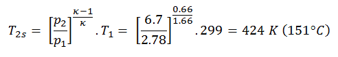
Using this temperature and the isentropic compressor efficiency we can calculate the heat added by the heat exchanger:
Qadd = cp(T3-T1) – (cp(T2s-T1)/ηK) = 5200.(1190 – 299) – 5200.(424-299)/0.87 = 4.633 MJ/kg – 0.747 MJ/kg = 3.886 MJ/kg
3)
The work done on the gas by the compressor in the isentropic compression process is:
WC,s = cp (T2s – T1) = 5200 x (424 – 299) = 0.650 MJ/kg
The real work done on the gas by the compressor in the adiabatic compression is then:
WC,real = cp (T2s – T1). ηC = 5200 x (424 – 299) / 0.87 = 0.747 MJ/kg
4)
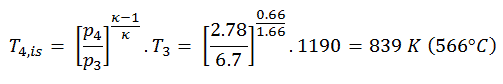
The turbine outlet temperature of the gas, T4,is, can be calculated using the same p, V, T Relation as in 2) but between states 3 and 4:
The previous equation follows that the outlet temperature of the gas, T4,is, is:
5)
The work done by gas turbine in the isentropic expansion is then:
WT,s = cp (T3 – T4s) = 5200 x (1190 – 839) = 1.825 MJ/kg
The real work done by gas turbine in the adiabatic expansion is then:
WT,real = cp (T3 – T4s) . ηT = 5200 x (1190 – 839) x 0.91 = 1.661 MJ/kg
6)
As was derived in the previous section, the thermal efficiency of an ideal Brayton cycle is a function of pressure ratio and κ:
therefore
ηth = 0.295 = 29.5%
The thermal efficiency can be also calculated using the work and the heat (without ηK):
ηth,s = (WT,s – WC,s) / Qadd,s = (1.825 – 0.650) / 3.983 = 0.295 = 29.5%
Finally, the thermal efficiency including isentropic turbine/compressor efficiency is:
ηth,real = (WT,real – WC,real) / Qadd = (1.661 – 0.747) / 3.886 = 0.235 = 23.5%