Control Volume – Control Volume Analysis
 A control volume is a fixed region in space chosen for the thermodynamic study of mass and energy balances for flowing systems. The boundary of the control volume may be a real or imaginary envelope. The control surface is the boundary of the control volume.
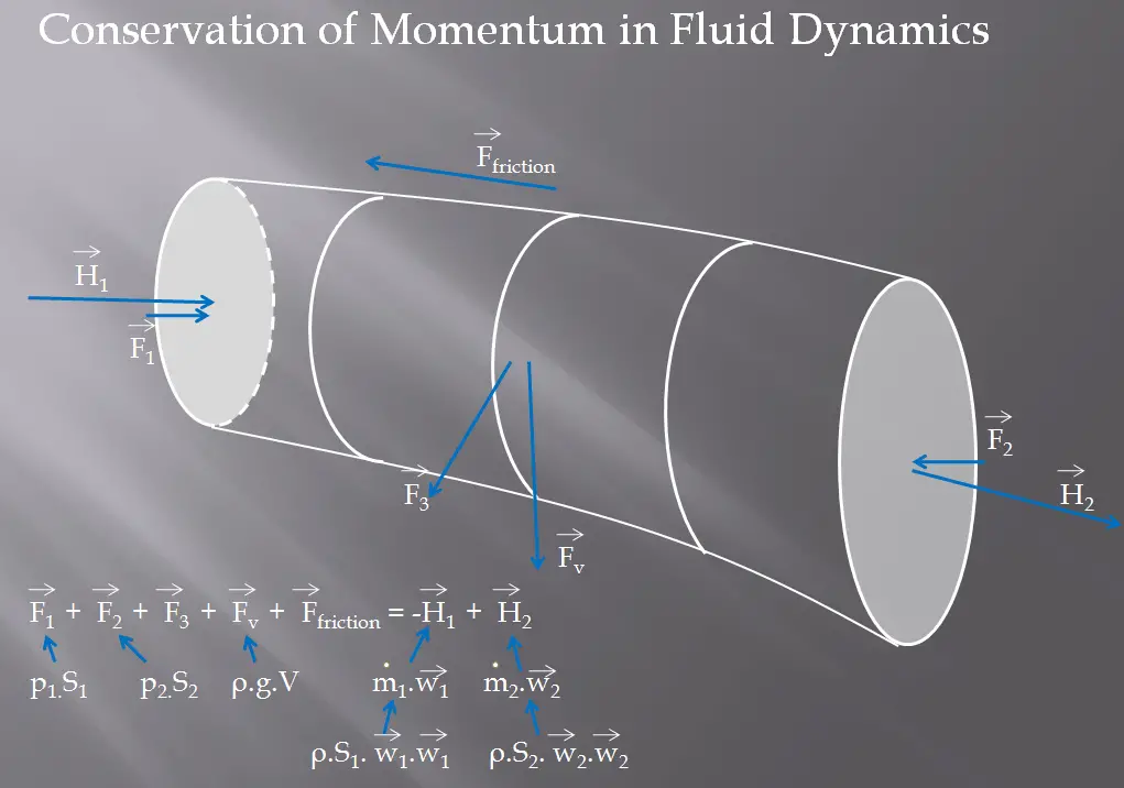
A control volume analysis can be used, for example, to determine the rate of change of momentum for a fluid. This analysis will consider a stream tube (control volume) as we did for the Bernoulli equation. In this control volume, any change in momentum of the fluid within a control volume is due to the action of external forces on the fluid within the volume.
See also: Momentum Formula.
As can be seen from the picture, the control volume method can analyze the law of conservation of momentum in the fluid. The control volume is an imaginary surface enclosing a volume of interest. The control volume can be fixed or moving, and it can be rigid or deformable. To determine all forces acting on the surfaces of the control volume, we have to solve the conservation laws in this control volume.
Choosing a Control Volume
A control volume can be selected as any arbitrary volume through which fluid flows. This volume can be static, moving, and even deforming during flow. To solve any problem, we have to solve basic conservation laws in this volume. It is very important to know all relative flow velocities to the control surface. Therefore it is very important to define exactly the boundaries of the control volume during an analysis.
Example: Water Jet Striking a Stationary Plate
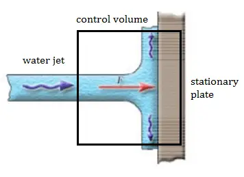 A stationary plate (e.g.,, blade of a watermill) deflects water flow at a velocity of 1 m/s and an angle of 90°. It occurs at atmospheric pressure, and the mass flow rate is equal to Q =1 m3/s.
- Calculate the pressure force.
- Calculate the body force.
- Calculate the total force.
- Calculate the resultant force.
Solution
- The pressure force is zero as the pressure at the inlet, and the outlets to the control volume are atmospheric.
- As the control volume is small, we can ignore the body force due to the weight of gravity.
- Fx = ρ.Q.(w1x – w2x) = 1000 . 1 . (1 – 0) = 1000 N
Fy = 0
F = (1000, 0) - The resultant force on the plane is the same magnitude but in the opposite direction as the total force F (friction and weight are neglected).
The water jet exerts on the plate the force of 1000 N in the x-direction.