Minor Head Loss – Local Losses
Any piping system contains different technological elements in the industry, such as bends, fittings, valves, or heated channels. These additional components add to the overall head loss of the system. Such losses are generally termed minor losses, although they often account for a major portion of the head loss. For relatively short pipe systems, with a relatively large number of bends and fittings, minor losses can easily exceed major losses (especially with a partially closed valve that can cause a greater pressure loss than a long pipe when a valve is closed or nearly closed, the minor loss is infinite).
The minor losses are commonly measured experimentally. The data, especially for valves, are somewhat dependent upon the particular manufacturer’s design.
Like pipe friction, the minor losses are roughly proportional to the square of the flow rate, and therefore they can be easily integrated into the Darcy-Weisbach equation. K is the sum of all of the loss coefficients in the length of pipe, each contributing to the overall head loss.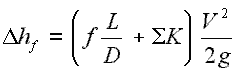
There are several methods how to calculate head loss from fittings, bends, and elbows. In the following section, these methods are summarized from the simplest to the most sophisticated.
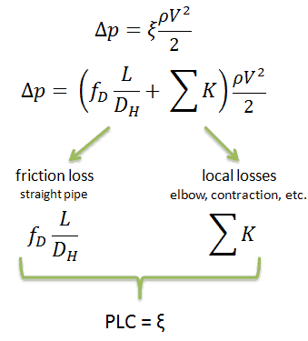
Pressure Loss Coefficient – PLC
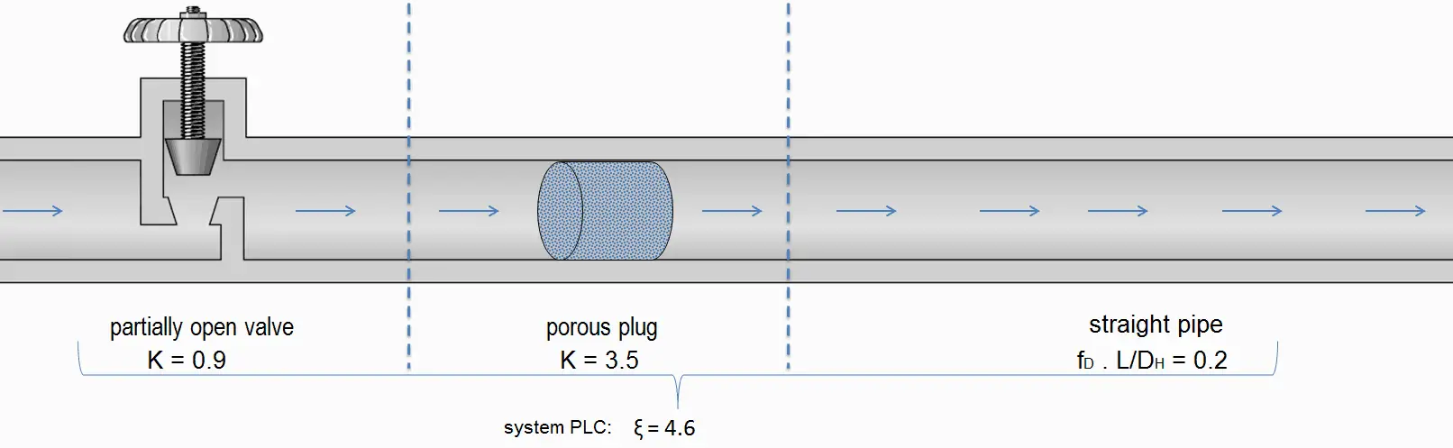
Sometimes, engineers use the pressure loss coefficient, PLC. It is noted K or ξ (pronounced “xi”). This coefficient characterizes pressure loss of a certain hydraulic system or a part of a hydraulic system. It can be easily measured in hydraulic loops. The pressure loss coefficient can be defined or measured for both straight pipes and especially for local (minor) losses.
Summary:
- Head loss of the hydraulic system is divided into two main categories:
- Major Head Loss – due to friction in straight pipes
- Minor Head Loss – due to components as valves, bends…
- A special form of Darcy’s equation can be used to calculate minor losses.
- The minor losses are roughly proportional to the square of the flow rate, and therefore they can be easily integrated into the Darcy-Weisbach equation through resistance coefficient K.
- As a local pressure loss, fluid acceleration in a heated channel can also be considered.
There are the following methods:
Why is head loss very important?
As can be seen from the picture, the head loss is forming key characteristic of any hydraulic system. In systems in which some certain flowrate must be maintained (e.g.,, to provide sufficient cooling or heat transfer from a reactor core), the equilibrium of the head loss and the head added by a pump determine the flow rate through the system.

Pressure Drop – Fuel Assembly
In general, total fuel assembly pressure drop is formed by fuel bundle frictional drop (dependent on relative roughness of fuel rods, Reynolds number, hydraulic diameter, etc.) and other pressure drops of structural elements (top and bottom nozzle, spacing grids, or mixing grids).
In general, it is not so simple to calculate pressure drops in fuel assemblies (especially the spacing grids), and it belongs to the key know-how of certain fuel manufacturers. Mostly, pressure drops are measured in experimental hydraulic loops rather than calculated.
Engineers use the pressure loss coefficient, PLC. It is noted K or ξ (pronounced “xi”). This coefficient characterizes pressure loss of a certain hydraulic system or a part of a hydraulic system. It can be easily measured in hydraulic loops. The pressure loss coefficient can be defined or measured for both straight pipes and especially for local (minor) losses.
Using the abovementioned example, the pressure loss coefficient (only frictional from the straight pipe) is equal to ξ = fDL/DH = 4.9. But the overall pressure loss coefficient (including spacing grids, top, and bottom nozzles, etc.) is usually about three times higher. This PLC (ξ = 4.9) causes that the pressure drop is of the order of (using the previous inputs) Δpfriction = 4.9 x 714 x 52/ 2 = 43.7 kPa (without spacing grids, top, and bottom nozzles). About three times higher real PLC means about three times higher Δpfuel will be.
The overall reactor pressure loss, Δpreactor, must include:
- downcomer and reactor bottom
- lower support plate
- fuel assembly including spacing grids, top, and bottom nozzles, and other structural components – Δpfuel
- upper guide structure assembly
In result the overall reactor pressure loss – Δpreactor is usually of the order of hundreds kPa (let say 300 – 400 kPa) for design parameters.