In fluid dynamics, the Darcy–Weisbach equation is a phenomenological equation, which relates the major head loss, or pressure loss, due to fluid friction along a given length of pipe to the average velocity. This equation is valid for fully developed, steady, incompressible single-phase flow.
The Darcy–Weisbach equation can be written in two forms (pressure loss form or head loss form). The head loss form can be written as:

where:
- Δh = the head loss due to friction (m)
- fD = the Darcy friction factor (unitless)
- L = the pipe length (m)
- D = the hydraulic diameter of the pipe D (m)
- g = the gravitational constant (m/s2)
- V = the mean flow velocity V (m/s)
where:
- Δp = the pressure loss due to friction (Pa)
- fD = the Darcy friction factor (unitless)
- L = the pipe length (m)
- D = the hydraulic diameter of the pipe D (m)
- g = the gravitational constant (m/s2)
- V = the mean flow velocity V (m/s)
___________
- Consider that the length of the pipe or channel is doubled, the resulting frictional head loss will double.
- At constant flow rate and pipe length, the head loss is inversely proportional to the 4th power of diameter (for laminar flow), and thus reducing the pipe diameter by half increases the head loss by a factor of 16. This is a very significant increase in head loss, and shows why larger diameter pipes lead to much smaller pumping power requirements.
- Since the head loss is roughly proportional to the square of the flow rate, then if the flow rate is doubled, the head loss increases by a factor of four.
- The head loss is reduced by half (for laminar flow) when the fluid’s viscosity is reduced by half.
https://commons.wikimedia.org/w/index.php?curid=4681366
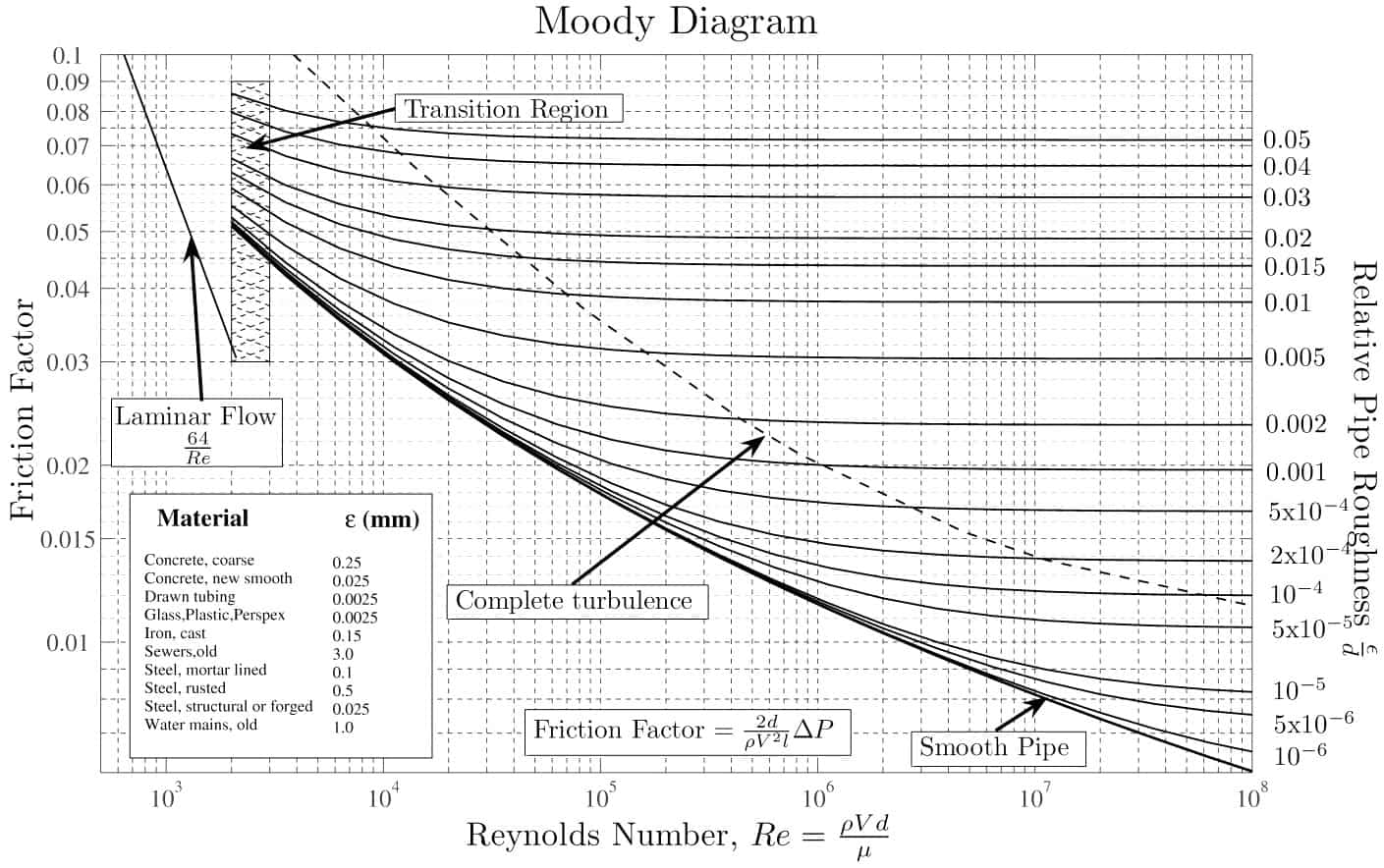
With the exception of the Darcy friction factor, each of these terms (the flow velocity, the hydraulic diameter, the length of a pipe) can be easily measured. The Darcy friction factor takes the fluid properties of density and viscosity into account, along with the pipe roughness. This factor may be evaluated by the use of various empirical relations, or it may be read from published charts (e.g., Moody chart).
Summary:
- Head loss of hydraulic system is divided into two main categories:
- Major Head Loss – due to friction in straight pipes
- Minor Head Loss – due to components as valves, bends…
- Darcy’s equation can be used to calculate major losses.
- The friction factor for fluid flow can be determined using a Moody chart.
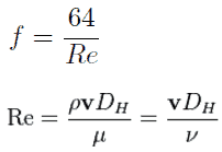
- The friction factor for laminar flow is independent of roughness of the pipe’s inner surface. f = 64/Re
- The friction factor for turbulent flow depends strongly on the relative roughness. It is determined by the Colebrook equation. It must be noted, at very large Reynolds numbers, the friction factor is independent of the Reynolds number.
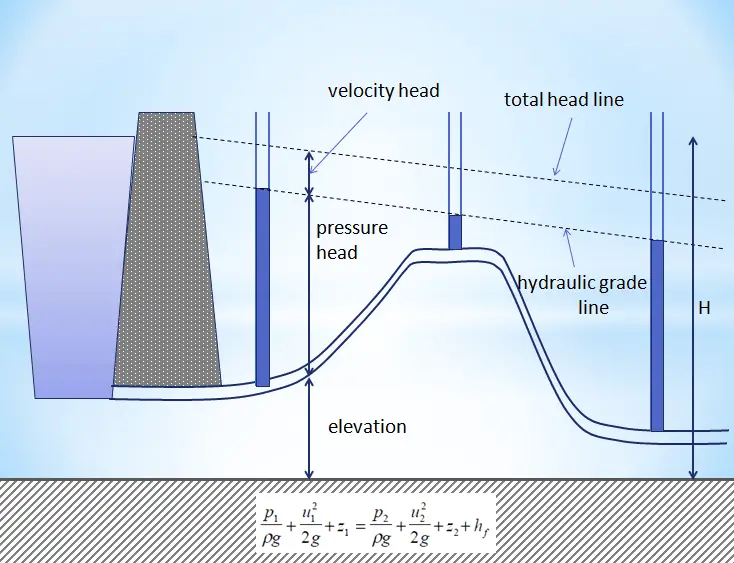
Why is head loss very important?
As can be seen from the picture, the head loss is forms key characteristic of any hydraulic system. In systems where some certain flowrate must be maintained (e.g.,, to provide sufficient cooling or heat transfer from a reactor core), the equilibrium of the head loss and the head added by a pump determine the flow rate through the system.

The exit is at standard atmospheric pressure (101 kPa) and is 200 m higher.
Calculate the frictional head loss Hf, and compare it to the flow v2/(2g) velocity head.
Solution:
Since the pipe diameter is constant, the average velocity and velocity head is the same everywhere:
vout = Q/A = 75 [m3/h] * 3600 [s/h] / 0.0113 [m2] = 1.84 m/s
Velocity head:
Velocity head = vout2/(2g) = 1.842 / 2*9.81 = 0.173 m
In order to find the frictional head loss, we have to use extended Bernoulli’s equation:
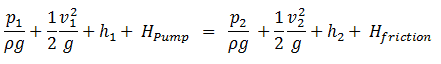
Head loss:
2 400 000 [Pa] / 1000 [kg/m3] * 9.81 [m/s2] + 0.173 [m] + 0 [m] = 101 000 [Pa] / 1000 [kg/m3] * 9.81 [m/s2] + 0.173 [m]+ 200 [m] + Hf
Hf = 244.6 – 10.3 – 200 = 34.3 m
where:
Since the Reynolds number is inverse proportional to viscosity, then the resulting head loss becomes proportional to viscosity. Therefore, the head loss is reduced by half when the viscosity of the fluid is reduced by half, when the flow rate and thus the average velocity are held constant.