Article Summary & FAQs
What is major head loss?
In fluid flow, major head loss or friction loss is the loss of pressure or “head” in pipe flow due to the effect of the fluid’s viscosity near the surface of the pipe or duct.
Key Facts
- Head loss of the hydraulic system is divided into two main categories:
- Major Head Loss – due to friction in straight pipes
- Minor Head Loss – due to components as valves, bends…
- Major head losses are a function of:
- flow regime (i.e., Reynolds number)
- flow velocity
- pipe diameter and its length
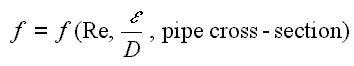
- friction factor (flow regime (i.e., Reynolds number), relative roughness)
- Darcy’s equation can be used to calculate major losses. The friction factor for fluid flow can be determined using a Moody chart.
- The Darcy friction factor is a dimensionless quantity used in the Darcy–Weisbach equation to describe frictional losses in pipe or duct and open-channel flow. This is also called the Darcy–Weisbach friction factor, resistance coefficient, or simply friction factor.
- The Colebrook correlation relates the Darcy friction factor, Reynolds number, and the relative roughness for fully developed flow in a circular pipe.
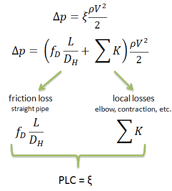
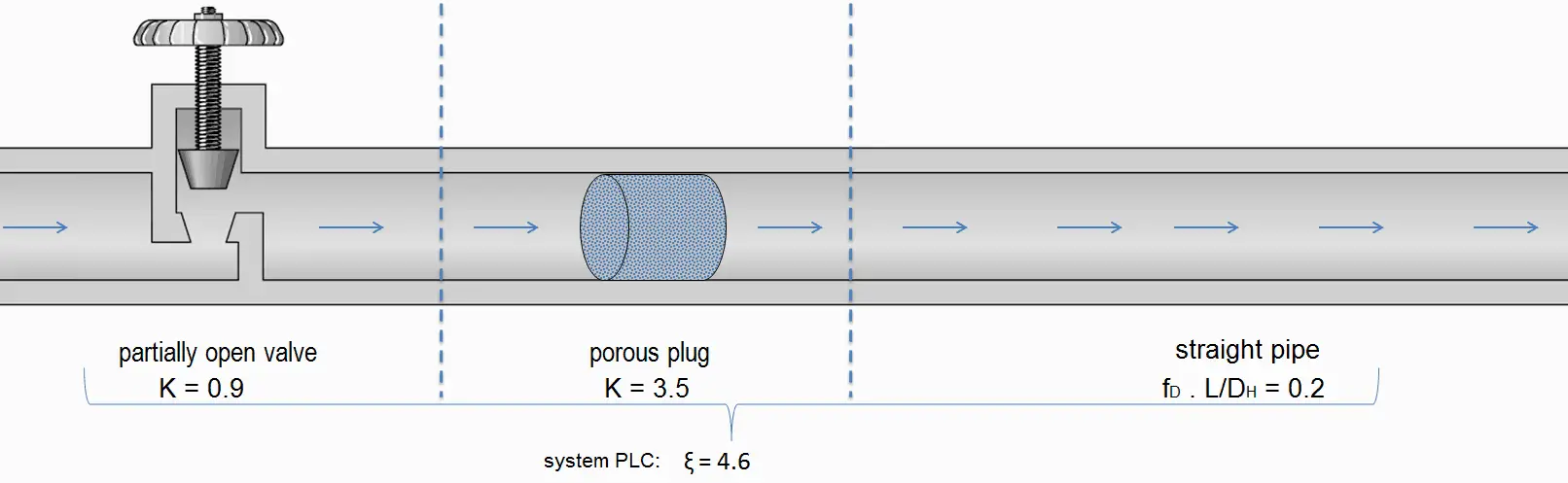
- Sometimes, engineers use the pressure loss coefficient, PLC. It is noted K or ξ (pronounced “xi”). This coefficient characterizes pressure loss of a certain hydraulic system or a part of a hydraulic system.
- An increasing Reynolds number indicates increasing turbulence of flow. As can be seen from the Moody chart, the Darcy friction factor also depends on the flow regime (i.e., on the Reynolds number).
Sometimes, engineers use the pressure loss coefficient, PLC. It is noted K or ξ (pronounced “xi”). This coefficient characterizes pressure loss of a certain hydraulic system or a part of a hydraulic system. It can be easily measured in hydraulic loops. The pressure loss coefficient can be defined or measured for both straight pipes and especially for local (minor) losses.
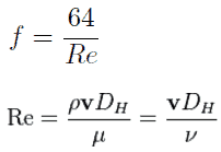
The Darcy friction factor for laminar (slow) flows is a consequence of Poiseuille’s law that and it is given by the following equations:
The most common method to determine a friction factor for turbulent flow is to use the Moody chart. The Moody chart (also known as the Moody diagram) is a log-log plot of the Colebrook correlation that relates the Darcy friction factor, Reynolds number, and the relative roughness for fully developed flow in a circular pipe. The Colebrook–White equation:
Major Head Loss – Frictional Loss
Major losses, which are associated with frictional energy loss per length of the pipe, depends on the flow velocity, pipe length, pipe diameter, and a friction factor based on the roughness of the pipe and whether the flow is laminar or turbulent (i.e., the Reynolds number of the flow).
Although the head loss represents a loss of energy, it does not represent a loss of total energy of the fluid. The total energy of the fluid is conserved as a consequence of the law of conservation of energy. In reality, the head loss due to friction results in an equivalent increase in the fluid’s internal energy (temperature increases).
By observation, the major head loss is roughly proportional to the square of the flow rate in most engineering flows (fully developed, turbulent pipe flow).
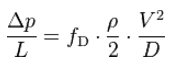
The most common equation used to calculate major head losses in a tube or duct is the Darcy–Weisbach equation.
In fluid dynamics, the head is a concept that relates the energy in an incompressible fluid to the height of an equivalent static column of that fluid. The units for all the different forms of energy in Bernoulli’s equation can also be measured in distance units. Therefore these terms are sometimes referred to as “heads” (pressure head, velocity head, and elevation head). Head is also defined for pumps. This head is usually referred to as the static head and represents the maximum height (pressure) it can deliver. Therefore the characteristics of all pumps can usually be read from their Q-H curve (flow rate – height).
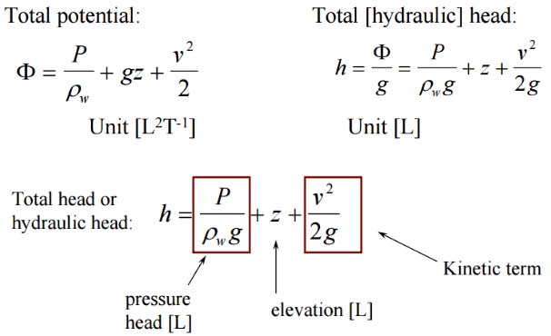
There are four types of potential (head):
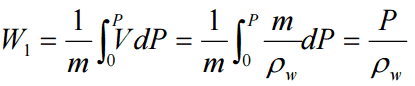
- Pressure potential – Pressure head: The pressure head represents the flow energy of a column of fluid whose weight is equivalent to the pressure of the fluid.
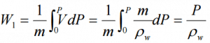 ρw: density of water assumed to be independent of pressure
 - Elevation potential – Elevation head: The elevation head represents the potential energy of a fluid due to its elevation above a reference level.
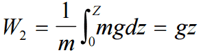
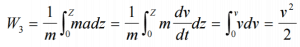
- Kinetic potential – Kinetic head: The kinetic head represents the kinetic energy of the fluid. The height in feet is that a flowing fluid would rise in a column if all of its kinetic energy were converted to potential energy.

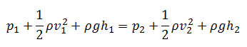
The sum of the elevation head, kinetic head, and pressure head of a fluid is called the total head. Thus, Bernoulli’s equation states that the total head of the fluid is constant.
Consider a pipe containing an ideal fluid. Suppose this pipe undergoes a gradual expansion in diameter. In that case, the continuity equation tells us that as the pipe diameter increases, the flow velocity must decrease to maintain the same mass flow rate. Since the outlet velocity is less than the inlet velocity, the kinetic head of the flow must decrease from the inlet to the outlet. If there is no change in the elevation head (the pipe lies horizontally), the decrease in the kinetic head must be compensated for by an increase in pressure head.
Darcy-Weisbach Equation
In fluid dynamics, the Darcy–Weisbach equation is a phenomenological equation, which relates the major head loss, or pressure loss, due to fluid friction along a given length of pipe to the average velocity. This equation is valid for fully developed, steady, incompressible single-phase flow.
The Darcy–Weisbach equation can be written in two forms (pressure loss form or head loss form). The head loss form can be written as:

where:
- Δh = the head loss due to friction (m)
- fD = the Darcy friction factor (unitless)
- L = the pipe length (m)
- D = the hydraulic diameter of the pipe D (m)
- g = the gravitational constant (m/s2)
- V = the mean flow velocity V (m/s)

where:
- Δp = the pressure loss due to friction (Pa)
- fD = the Darcy friction factor (unitless)
- L = the pipe length (m)
- D = the hydraulic diameter of the pipe D (m)
- g = the gravitational constant (m/s2)
- V = the mean flow velocity V (m/s)
___________
Evaluating the Darcy-Weisbach equation provides insight into factors affecting head loss in a pipeline.
- Consider that the length of the pipe or channel is doubled, the resulting frictional head loss will double.
- At constant flow rate and pipe length, the head loss is inversely proportional to the 4th power of diameter (for laminar flow). Thus, reducing the pipe diameter by half increases the head loss by a factor of 16. This is a significant increase in head loss and shows why larger diameter pipes lead to much smaller pumping power requirements.
- Since the head loss is roughly proportional to the square of the flow rate, then if the flow rate is doubled, the head loss increases by a factor of four.
- The head loss is reduced by half (for laminar flow) when the fluid’s viscosity is reduced by half.
https://commons.wikimedia.org/w/index.php?curid=4681366
Except for the Darcy friction factor, each of these terms (the flow velocity, the hydraulic diameter, the length of a pipe) can be easily measured. The Darcy friction factor takes the fluid properties of density and viscosity into account, along with the pipe roughness. This factor may be evaluated using various empirical relations, or it may be read from published charts (e.g.,, Moody chart).
The exit is at standard atmospheric pressure (101 kPa) and is 200 m higher.
Calculate the frictional head loss Hf, and compare it to the flow v2/(2g) the velocity head.
Solution:
Since the pipe diameter is constant, the average velocity and velocity head is the same everywhere:
vout = Q/A = 75 [m3/h] * 3600 [s/h] / 0.0113 [m2] = 1.84 m/s
Velocity head:
Velocity head = vout2/(2g) = 1.842 / 2*9.81 = 0.173 m
In order to find the frictional head loss, we have to use extended Bernoulli’s equation:
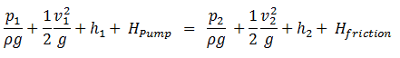
Head loss:
2 400 000 [Pa] / 1000 [kg/m3] * 9.81 [m/s2] + 0.173 [m] + 0 [m] = 101 000 [Pa] / 1000 [kg/m3] * 9.81 [m/s2] + 0.173 [m]+ 200 [m] + Hf
Hf = 244.6 – 10.3 – 200 = 34.3 m
Darcy Friction Factor
There are two common friction factors in use, the Darcy and the Fanning friction factors.
The Darcy friction factor is a dimensionless quantity used in the Darcy–Weisbach equation to describe frictional losses in pipe or duct and open-channel flow. This is also called the Darcy–Weisbach friction factor, resistance coefficient, or simply friction factor.
The friction factor has been determined to depend on the Reynolds number for the flow and the degree of roughness of the pipe’s inner surface (especially for turbulent flow). The friction factor of laminar flow is independent of the roughness of the pipe’s inner surface.
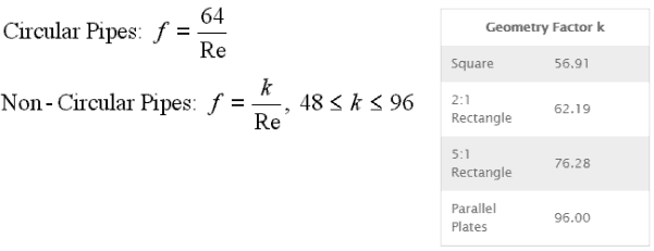
The pipe cross-section is also important, as deviations from circular cross-sections will cause secondary flows that increase the head loss. Non-circular pipes and ducts are generally treated by using the hydraulic diameter.
Relative Roughness
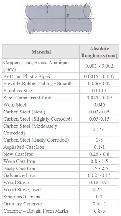
The quantity used to measure the roughness of the pipe’s inner surface is called the relative roughness, and it is equal to the average height of surface irregularities (ε) divided by the pipe diameter (D).
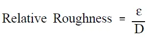
where both the average height surface irregularities and the pipe diameter are in millimeters.
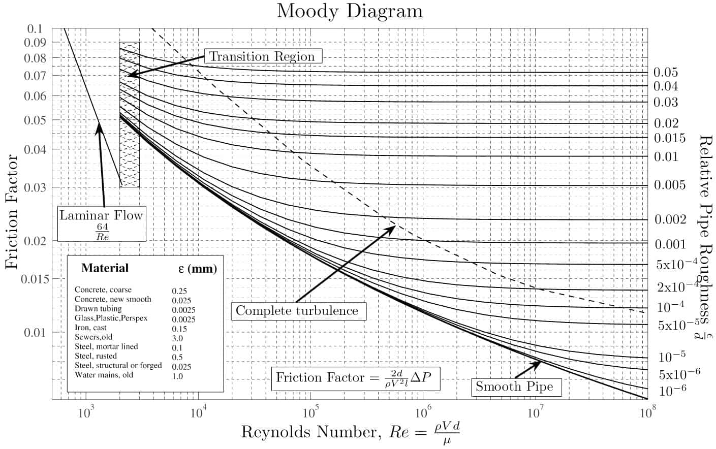
If we know the relative roughness of the pipe’s inner surface, then we can obtain the value of the friction factor from the Moody Chart.
The Moody chart (also known as the Moody diagram) is a graph in a non-dimensional form that relates the Darcy friction factor, Reynolds number, and the relative roughness for fully developed flow in a circular pipe.
Solution:
The relative roughness is equal to ε = 0.035 / 700 = 5 x 10⁻⁵. Using the Moody Chart, a Reynolds number of 50 000 000 intersects the curve corresponding to a relative roughness of 5 x 10⁻⁵ at a friction factor of 0.011.
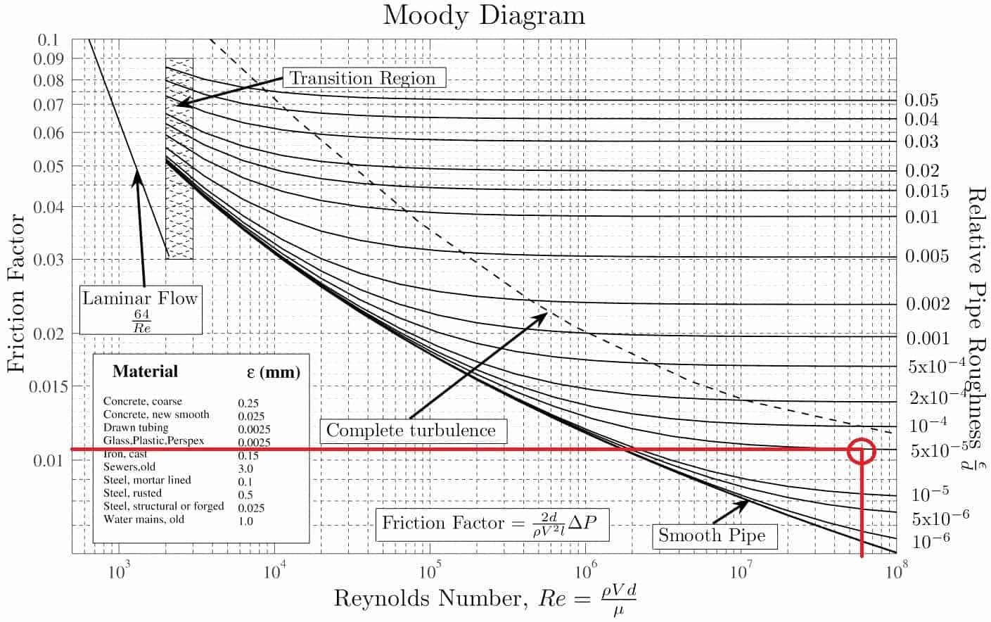
Source: Donebythesecondlaw at the English language Wikipedia, CC BY-SA 3.0, https://commons.wikimedia.org/w/index.php?curid=4681366
Darcy Friction Factor for various flow regime
The most common classification of flow regimes is according to the Reynolds number. The Reynolds number is a dimensionless number comprised of the physical characteristics of the flow, and it determines whether the flow is laminar or turbulent. An increasing Reynolds number indicates increasing turbulence of flow. As can be seen from the Moody chart, the Darcy friction factor also highly depends on the flow regime (i.e., on the Reynolds number).
The Darcy friction factor for laminar (slow) flows is a consequence of Poiseuille’s law that and it is given by the following equations:
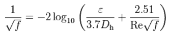
The most common method to determine a friction factor for turbulent flow is to use the Moody chart. The Moody chart (also known as the Moody diagram) is a log-log plot of the Colebrook correlation that relates the Darcy friction factor, Reynolds number, and the relative roughness for fully developed flow in a circular pipe. The Colebrook–White equation:
which is also known as the Colebrook equation, expresses the Darcy friction factor f as a function of pipe relative roughness ε / Dh and Reynolds number.
In 1939, Colebrook found an implicit correlation for the friction factor in round pipes by fitting the data of experimental studies of turbulent flow in smooth and rough pipes.
For hydraulically smooth pipe and the turbulent flow (Re < 105), the friction factor can be approximated by the Blasius formula:
f = (100.Re)-¼
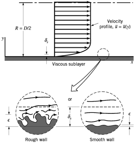 It must be noted that the friction factor is independent of the Reynolds number at very large Reynolds numbers. This is because the thickness of the laminar sublayer (viscous sublayer) decreases with increasing Reynolds number. For very large Reynolds numbers, the thickness of the laminar sublayer is comparable to the surface roughness, and it directly influences the flow. The laminar sublayer becomes so thin that the surface roughness protrudes into the flow. The frictional losses, in this case, are produced in the main flow primarily by the protruding roughness elements, and the contribution of the laminar sublayer is negligible.
Examples
where:
Since the Reynolds number is inverse proportional to viscosity, the resulting head loss becomes proportional to viscosity. Therefore, the head loss is reduced by half when the fluid’s viscosity is reduced by half, when the flow rate and thus the average velocity are held constant.