By definition, multiphase flow is the interactive flow of two or more distinct phases with common interfaces in, say, a conduit. Each phase, representing a volume fraction (or mass fraction) of solid, liquid, or gaseous matter, has its own properties, velocity, and temperature.
A multiphase flow can be a simultaneous flow of:
- Materials with different states or phases (e.g.,, water-steam mixture).
- Materials with different chemical properties but in the same state or phase (e.g.,, oil droplets in water).
 There are many combinations in industrial processes, but the most common being the simultaneous flow of steam and liquid water (as encountered in steam generators and condensers). In reactor engineering, a great deal of study has been performed on the nature of two-phase flow in case of a loss-of-coolant accident (LOCA), an accident of importance in reactor safety, and all thermal-hydraulic analyses (DNBR analyses).
Characteristics of Two-phase Fluid Flow
All two-phase flow problems have features that are characteristically different from those found in single-phase problems.
- In the case of steam and liquid water, the density of the two phases differs by a factor of about 1000. Therefore the influence of gravitational body force on multiphase flows is of much greater importance than in the case of single-phase flows.
- The sound speed changes dramatically for materials undergoing a phase change and can be orders of magnitude different. This significantly influences a flow through an orifice.
- The relative concentration of different phases is usually a dependent parameter of great importance in multiphase flows, while it is a parameter of no consequence in single-phase flows.
- The phase change means flow-induced pressure drops can cause further phase change (e.g.,, water can evaporate through an orifice), increasing the relative volume of the gaseous, compressible medium and increasing efflux velocities, unlike single-phase incompressible flow where decreasing of an orifice would decrease efflux velocities.
- The spatial distribution of the various phases in the flow channel strongly affects the flow behavior.
- There are many types of instabilities in multiphase flow.
Basic Parameters of Two‐phase Fluid Flow
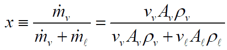
This section will consider the simultaneous flow of gas (or vapor) and liquid water (as encountered in steam generators and condensers) in concurrent flow through a duct with cross-sectional area A. The subscripts “v” and “ℓ” indicate the vapor and liquid phase, respectively. Fundamental parameters that characterize this flow are:
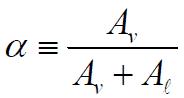
Various geometric definitions are used for specifying this parameter. The void fraction in a two-phase fluid flow may be defined as:
- The fraction of the channel volume that is occupied by the gas phase. This void fraction is known as the volumetric void fraction.
- The fraction of the channel cross-sectional area that is occupied by the gas phase. This void fraction is known as the cross-sectional void fraction.
- The local void fraction refers to that at one single point or very small volume. Therefore it takes the values of 1 or 0.
For further purposes, we will assume a void fraction to be the fraction of the channel cross-sectional area that is occupied by the gas phase (i.e., cross-sectional void fraction) defined as:
The void fraction is important in the two-phase flow because it influences key physical parameters, such as viscosity, pressure drop, and heat transfer.
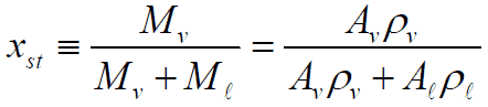
The static quality in a two-phase fluid flow is defined as:

In the homogeneous equilibrium model (HEM) of two-phase flow, the slip ratio is by definition assumed to be unity (there is no slip). However, most industrial two-phase flows have a different velocity of the gas and liquid phases. These can differ significantly. The models that account for the existence of the slip are called separated flow models.
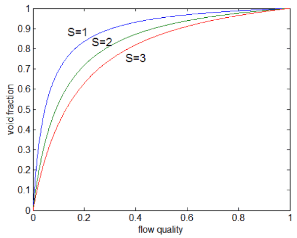
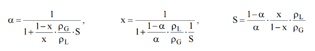
The relations between x, α, and S can be deducted, and the result is:
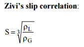
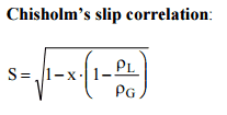
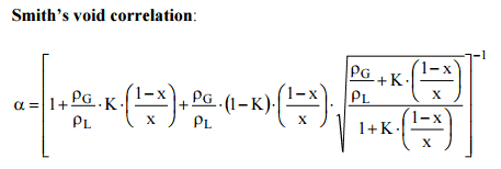
The reason for defining the void fraction and the slip ratio is that they also make it possible to calculate the pressure drop of the two-phase flow. Several correlations for calculating the slip ratio, S, and the void fraction are presented in the literature. The following correlations are given in order of increasing accuracy.

In engineering multiphase flows and flows in porous media, superficial velocity is commonly used because it is an unambiguous value. In contrast, real velocity is often spatially dependent and subject to many assumptions.
Superficial velocity can be expressed as:
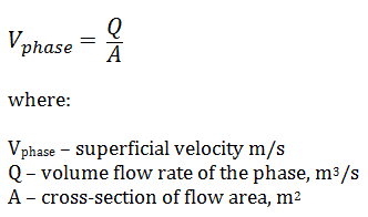
For better understanding, let us consider a pipe with a 0.1 m2 cross-section of flow area. Assume that the flow rate is 1 m3/s. For single-phase fluid flow, the superficial velocity will be equal to real fluid velocity, which will be 10 m/s.
For two-phase fluid flow (e.g.,, vapor-liquid flow), the situation will be different. Assuming the slip ratio is unity, both phases have taken separately, will have superficial velocities of 5 m/s. The resulting real velocity will then be equal to 10 m/s. If the two phases have different velocities (with slip), the situation will be more complicated.
Flow Patterns – Two-phase Flow
One of the most challenging aspects of dealing with the two-phase flow or multiphase flow is the fact that it can take many different forms. Spatial distributions and velocities of the liquid and vapor phases in the flow channel are very important aspects in many engineering branches. Pressure drops and heat transfer coefficients strongly depend on the local flow structure, and thus it is important in the engineering of nuclear reactors. The observed flow structures are defined as two-phase flow patterns, and these have particular identifying characteristics. These different flow patterns have been categorized according to the direction of flow relative to gravitational acceleration.
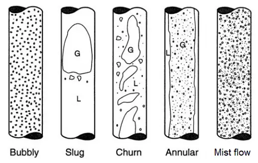
- Flow patterns in vertical tubes
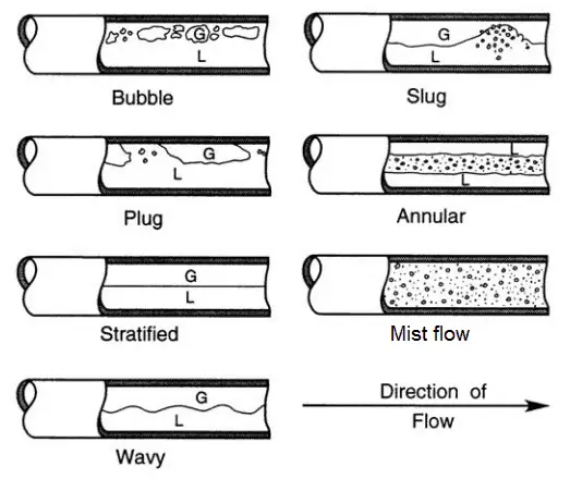
- Flow patterns in horizontal tubes
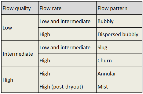
The main flow regimes in vertical tubes are shown in the table. It must be noted values of flow quality and flow rate is dependent on the fluid and pressure. In horizontal tubes, there can also be stratified flow (especially at low flow rates), at which the two phases separate under the effect of gravity.
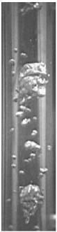
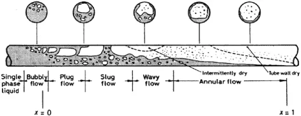
The vapor/gas phase tends to be distributed as small bubbles at low vapor flow rates for a constant liquid flow rate. Increasing void fraction causes the agglomeration of bubbles into larger plugs and slugs. Further agglomeration of slugs, caused by further increasing void fraction, causes separation of the phases into annular patterns wherein liquid concentrates at the channel wall, and vapor flows in the central core of the vertical channel.
For horizontal channels, gravitational force tends to drain the liquid annulus toward the bottom of the channel, resulting in stratified flow. The gravitational force acting on the liquid phase can be overcome by kinetic forces at high flow rates, causing stratified flows to revert to annular flows. At very high flow rates, the annular film is thinned by the shear of the vapor core, and all the liquid is entrained as droplets in the vapor phase. This flow regime is usually known as the mist flow.
See also: Engineering Data Book III, Thome, J.R., Wolverine Tube Inc, 2004.
Flow Patterns – Vertical Tubes
Both adiabatic annular flows (without heat exchange) and diabatic annular flows (with heat exchange) occur in industrial applications:
- in steam generators
- condensers
- boiling water reactors – BWR
- during accidents in PWRs
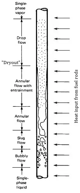
In the case of BWR, in which a phase transition (evaporation) occurs, detailed knowledge of this flow regime is highly important. At given combinations of flow rate through a channel, pressure, flow quality, and linear heat rate, the liquid wall film may exhaust, and the wall may be dried out. This phenomenon is usually known as “dry out”. Dryout is accompanied by a rapid rise in wall temperature and is important in the safety of BWRs.
Flow Patterns – Horizontal Tubes
Flow patterns during evaporation
The previous section describes various flow patterns and shortly describes their behavior. These flow patterns were considered to be at constant void fraction and constant superficial velocities. But many industrial applications have to consider a variable void fraction and variable superficial velocities. In the nuclear industry, we have to deal with flow patterns during evaporation (i.e., during changes in the void fraction).
Detailed knowledge of phase changes and the behavior of the flow during the phase change is one of the most important considerations in the design of a nuclear reactor, especially in the following applications:
 BWR – Boiling Water Reactors
- A boiling water reactor is cooled and moderated by water like a PWR, but at a lower pressure (7MPa), which allows the water to boil inside the pressure vessel producing the steam that runs the turbines. Evaporation, therefore, occurs directly in fuel channels. Therefore, BWRs are the best example for this area because coolant evaporation occurs at normal operation and is a very desired phenomenon.
- In BWRs, there is a phenomenon that is of the highest importance in reactor safety. This phenomenon is known as the “dry out” and is directly associated with changes in flow pattern during evaporation. At normal, the fuel surface is effectively cooled by boiling coolant. However, when the heat flux exceeds a critical value (CHF – critical heat flux), the flow pattern may reach the dry-out conditions (a thin film of liquid disappears). The heat transfer from the fuel surface into the coolant is deteriorated due to a drastically increased fuel surface temperature.
- PWR – Pressurized Water Reactors
- In PWRs at normal operation, the flow is considered to be single-phase. But a great deal of study has been performed on the nature of two-phase flow in case of transients and accidents (such as the loss-of-coolant accident – LOCA or trip of RCPs), which are of importance in reactor safety and in must be proved and declared in the Safety Analysis Report (SAR). In the case of PWRs, the problematic phenomenon is not the dry out. In the case of PWRs, the critical flow is an inverted annular flow. This flow occurs when a fuel rod cladding surface is overheated, which causes the formation of a local vapor layer, causing a dramatic reduction in heat transfer capability. This phenomenon is known as a departure from nucleate boiling – DNB. The difference in flow regime between post-dry outflow and post-DNB flow is depicted in the figure.
- In PWRs, evaporation also occurs in steam generators. Steam generators are heat exchangers that convert feedwater into steam from heat produced in a nuclear reactor core. The steam produced drives the turbine.

 Convective evaporation in a vertical channel is depicted in the figure. This figure shows the typical order of the flow regimes encountered from inlet to outlet of a heated channel. At the inlet, the liquid enters subcooled (at a lower temperature than saturation). In this region, the flow is single-phase. As the liquid heats up, the wall temperature correspondingly rises. As the wall temperature exceeds the saturation temperature (e.g.,, 285°C at 6.8 MPa), subcooled boiling begins. Bubbles nucleate in the superheated thermal boundary layer on the heated wall but tend to condense in the subcooled bulk.
Further increase in liquid temperature causes that the liquid bulk reaches its saturation temperature, and the convective boiling process passes through the bubbly flow into the slug flow. Increasing void fraction causes that the structure of the flow becomes unstable. The boiling process passes through the slug and churns flow into the annular flow regime with its characteristic annular film of the liquid. At given combinations of flow rate through a channel, pressure, flow quality, and linear heat rate, the liquid wall film may exhaust, and the wall may be dried out. At the dry-out point, the wall temperature significantly rises to dissipate the applied heat flux. The post-dry outflow (mist or drop flow) in the heated channel is undesirable because the presence of such a flow regime is accompanied with significantly higher wall temperatures and high fluctuation of wall temperatures.
At the inlet, the liquid enters subcooled (at a lower temperature than saturation). In this region, the flow is single-phase. As the liquid heats up, the wall temperature correspondingly rises. As the wall temperature exceeds the saturation temperature (e.g.,, 285°C at 6.8 MPa), subcooled boiling begins. The convective boiling process passes through bubbly, plug regimes, and flow can be either stratified or unstratified (depending on the flow velocity). As can be seen, the channel dries out occurs at the top of the tube, where the film thickness is thinner due to gravitational force. Dryout then progresses around the perimeter from top to bottom along the channel.
Two-phase Pressure Drop
In the practical analysis of piping systems, the quantity of most importance is the pressure loss due to viscous effects along the length of the system, as well as additional pressure losses arising from other technological equipments like valves, elbows, piping entrances, fittings, and tees.
In contrast, to single-phase pressure drops, calculation and prediction of two-phase pressure drops is a much more complex problem, and leading methods differ significantly. Experimental data indicates that the frictional pressure drop in the two-phase flow (e.g.,, in a boiling channel) is substantially higher than for a single-phase flow with the same length and mass flow rate. Explanations include an apparently increased surface roughness due to bubble formation on the heated surface and increased flow velocities.
Pressure Drop – Homogeneous Flow Model
The simplest approach to predicting two-phase flows is to treat the entire two-phase flow as if it were all liquid, except flowing at the two-phase mixture velocity. The two-phase pressure drops for flows inside pipes and channels are the sum of three contributions:
- the static pressure drop ∆pstatic (elevation head)
- the momentum pressure drop ∆pmom (fluid acceleration)
- the frictional pressure drop ∆pfrict
The total pressure drop of the two-phase flow is then:
∆ptotal = ∆pstatic + ∆pmom + ∆pfrict
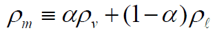
The static and momentum pressure drops can be calculated similarly as in the case of single-phase flow and using the homogeneous mixture density:
The most problematic term is the frictional pressure drop ∆pfrict, which is based on the single-phase pressure drop multiplied by the two-phase correction factor (homogeneous friction multiplier – Φlo2). By this approach, the frictional component of the two-phase pressure drop is:

where (dP/dz)2f is frictional pressure gradient of two-phase flow and (dP/dz)1f is frictional pressure gradient if an entire flow (of total mass flow rate G) flows like a liquid in the channel (standard single-phase pressure drop). The term Φlo2 is the homogeneous friction multiplier that can be derived according to various methods. One of the possible multipliers is equal to Φlo2 = (1+xg(ρl/ρg – 1)) and therefore:
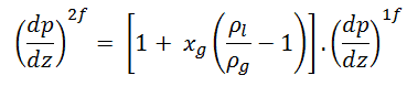
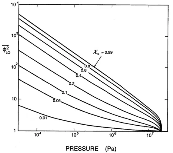
As can be seen, this simple model suggests that the two-phase frictional losses are in any event higher than the single-phase frictional losses. The homogeneous friction multiplier increases rapidly with flow quality.
Typical flow qualities in steam generators and BWR cores are on the order of 10 to 20 %. The corresponding two-phase frictional loss would be 2 – 4 times that in an equivalent single-phase system.
Source: http://authors.library.caltech.edu/25021/1/chap8.pdf
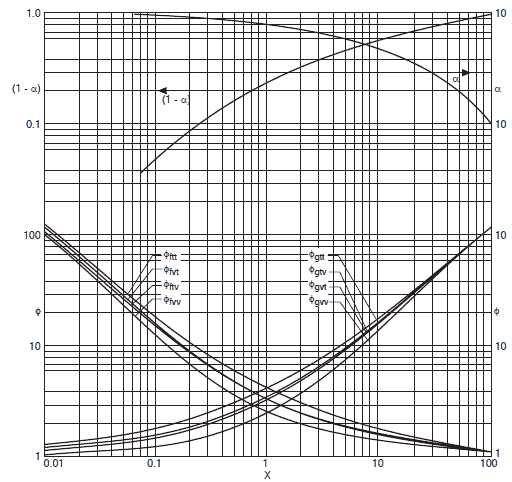
In this model, the phases are considered to be flowing separately in the channel, each occupying a given fraction of the channel cross-section and each with a given velocity. It is obvious the predicting the void fraction is very important for these methods. Numerous methods are available for predicting the void fraction.
The method of Lockhart and Martinelli is the original method that predicted the two-phase frictional pressure drop based on a friction multiplicator for the liquid-phase or the vapor-phase:
∆pfrict = Φltt2 . ∆pl (liquid-phase ∆p)
∆pfrict = Φgtt2 . ∆pg (vapor-phase ∆p)
The single-phase friction factors of the liquid fl and the vapor fg are based on the single-phase flowing alone in the channel, in either viscous laminar (v) or turbulent (t) regimes.
∆pl can be calculated classically but with the application of (1-x)2 in the expression and ∆pg with the application of vapor quality x2, respectively.
The two-phase multipliers Φltt2 and Φgtt2 are equal to:
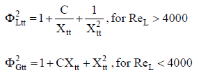
where Xtt is the Martinelli’s parameter defined as:
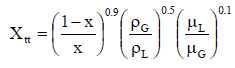
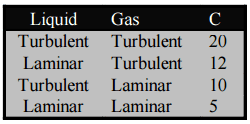 and the value of C in these equations depends on the flow regimes of the liquid and vapor. These values are in the following table.
The Lockhart-Martinelli correlation is adequate for two-phase flows at low and moderate pressures. Martinelli and Nelson’s (1948) and Thom (1964) revised models are recommended for applications at higher pressures.

Flow Instability
In general, there are many instabilities that may occur in two-phase systems. In nuclear engineering, the study of the multiphase flow stability is important in the accident management of pressurized water reactors and the highest importance in normal/abnormal conditions in boiling water reactors.
In PWRs at normal operation, the flow is considered to be single-phase. But a great deal of study has been performed on the flow instability in case of transients and accidents (such as the loss-of-coolant accident – LOCA or trip of RCPs with the presence of natural circulation), in which flow oscillations or flow reversals may occur.
Flow oscillations are variations in flow caused by void formations, which are undesirable for several reasons.
- Flow oscillations can cause undesirable mechanical stress on fuel components (such as spacing grids). This can lead to the failure of those components due to fatigue.
- Flow oscillations affect the local heat transfer characteristics. In the case of PWRs, the critical safety issue is named DNB (departure from nucleate boiling), which causes the formation of a local vapor layer, causing a dramatic reduction in heat transfer capability. It has been found through testing that the critical heat flux (CHF) required for departure from nucleate boiling (DNB) can be lowered by as much as 40% when the flow is oscillating. This severely reduces the thermal limit and the power density along the length of the reactor core.
Flow oscillations can be a problem during natural circulation operations (e.g.,, after tripping of all RCPs). Natural circulation is an important design feature and ultimate heat removal mechanism. Because of the low flow rates present, coolant boiling may occur, which may form flow oscillations. During natural circulation, the steam bubbles formed during a flow oscillation may have enough effect to actually cause complete flow reversal in the affected channel.
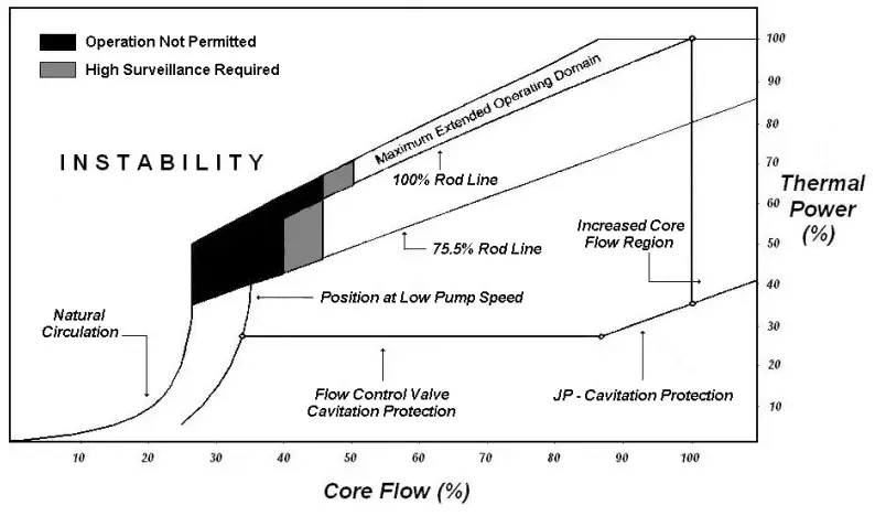
In BWRs, evaporation of coolant occurs at normal operation, and it is a very desired phenomenon. On the other hand, convective evaporation in the fuel channel causes that the flow pattern changes along the fuel channel depending on the flow rate and thermal power. It has been found that there are instability regions in which two-phase flow instabilities may arise. These two-phase flow instabilities are undesirable as they can result in mechanical vibrations and system control problems, affect normal operation, restrict operating parameters, and influence reactor safety. It must be noted flow stability in BWRs is not a major issue for many years because it is a well-known phenomenon.
In general, there are many classifications of flow instabilities. The following classification is based upon thermal-hydraulic fundamental mechanisms:
The static instabilities are:
- Flow excursion
- Boiling crisis
- Relaxation types, including flow pattern transition
The dynamic instabilities are:
- Density wave oscillations
- Pressure drop oscillations
- Thermal oscillations.
The proper characterization of the instabilities and the condition for their occurrence can determine the optimal and safe operation of the systems. The most accepted explanation for the occurrence of the dynamic type of instabilities is called density wave oscillations (DWO).
The density wave causes a delay in the local pressure drop caused by a change in inlet flow. Because of this delay, the sum of all local pressure drops may result in a total drop that is out-of-phase with the inlet flow. The basic mechanism causing flow instabilities in BWRs is the density wave. The characteristic periods of these oscillations are associated with the time required for a fluid particle to travel through the entire loop.
Types of instabilities observed in BWRs
- Control System Instabilities. Control system instabilities are related to the action of controllers that, through actuators, attempt to regulate some of the variables of the reactor.
- Channel Flow Instabilities. This type of instability can be described as follows: Let assume a flow perturbation. This perturbation causes a “wave” of voids traveling upward through the channel, producing a two-phase pressure drop (pressure drop increases significantly as void fraction increases) that is delayed with respect to the original perturbation. An increase in channel pressure drop (density wave) may lead to instability in the flow rate.
- Coupled Neutronic-Thermohydraulic Instability. The dominant type of instabilities in commercial BWRs is the coupled neutronic-thermohydraulic instability (also known as reactivity instability). The power generation in BWRs is directly related to the fuel neutron flux, which is strongly related to the average void fraction in the core channels. This effect is known as reactivity feedback. The reactivity feedback caused by changes in void fraction (void coefficient) is delayed as the voids travel upward through the fuel channel. In some cases, the delay may be long enough, and the void feedback may be strong enough that the reactor configuration becomes unstable. In this case, the neutron flux may oscillate.
Special References:
- Francesco D’Auria, The BWR Stability Issue, THICKET 2008 – Session IX – Paper 26
- Dag Strømsvåg, Fundamental mechanisms of density wave oscillations and the effect of subcooling, NTNU, 2011.
- J. March-Leuba, Density -Wave Instabilities in Boiling Water Reactors. NUREG/CR-6003, ORNL, 1992.