According to 10 CFR Part 50; Criterion 11:
“The reactor core and associated coolant systems shall be designed so that in power operating range, the net effect of the prompt inherent nuclear feedback characteristics tends to compensate for a rapid increase in reactivity.
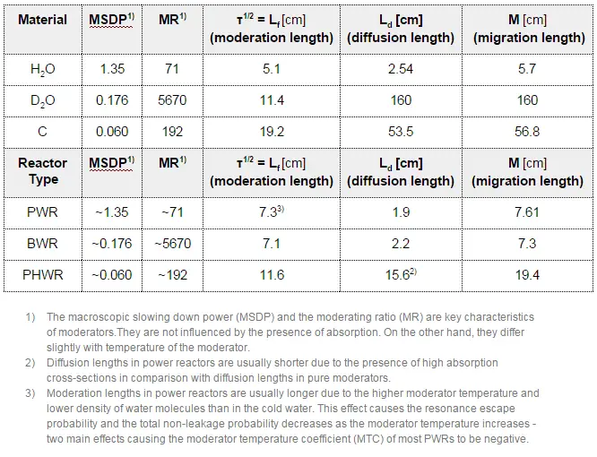
Up to this point, we have discussed the response of the neutron population in a nuclear reactor to an external reactivity input. There was applied an assumption that the level of the neutron population does not affect the properties of the system, especially that the neutron power (power generated by chain reaction) is sufficiently low that the reactor core does not change its temperature (i.e.,, reactivity feedbacks may be neglected). For this reason, such treatments are frequently referred to as zero-power kinetics.
However, in an operating power reactor, the neutron population is always large enough to generate heat. It is the main purpose of power reactors to generate a large amount of heat. This causes the system’s temperature to change and material densities to change as well (due to the thermal expansion).
Source: Youtube
See also: General Atomics – TRIGA
Example: Change in the moderator temperature.
Negative feedback as the moderator temperature effect influences the neutron population in the following way. If the temperature of the moderator is increased, negative reactivity is added to the core. This negative reactivity causes reactor power to decrease. As the thermal power decreases, the power coefficient acts against this decrease, and the reactor returns to the critical condition. The reactor power stabilizes itself. In terms of multiplication factor, this effect is caused by significant changes in the resonance escape probability and total neutron leakage (or in the thermal utilization factor when the chemical shim is used).
↑TM ⇒ ↓keff = η.ε. ↓p .f. ↓Pf . ↓Pt (EOC)
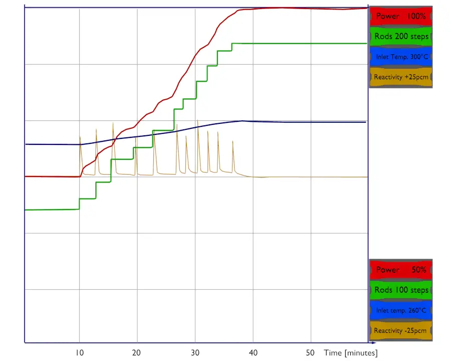
Change of the neutron leakage. Since both (Pf and Pt) are affected by a change in moderator temperature in a heterogeneous water-moderated reactor and the directions of the feedbacks for both negative, the resulting total non-leakage probability is also sensitive to the change in the moderator temperature. As a result, an increase in the moderator temperature causes that the probability of leakage to increase. In the case of the fast neutron leakage, the moderator temperature influences macroscopic cross-sections for elastic scattering reaction (Σs=σs.NH2O) due to the thermal expansion of water, which increases the moderation length. This, in turn, causes an increase in the leakage of fast neutrons.
- For the thermal neutron leakage, there are two effects. Both processes have the same direction and together cause the increase in the thermal neutron leakage. This physical process is a part of the moderator temperature coefficient (MTC).
- Macroscopic cross-sections for elastic scattering reaction Σs=σs.NH2O, which significantly changes due to the thermal expansion of water. As the temperature of the core increases, the diffusion coefficient (D = 1/3.Σtr) increases.
- Microscopic cross-section (σa) for neutron absorption changes with core temperature. As the temperature of the core increases, the absorption cross-section decreases.
Examples: Change in the reactor power
change an operating parameter and not affect every other property of the core. Since it is difficult to separate all these effects (moderator, fuel, void, etc.), the power coefficient is defined. The power coefficient combines the Doppler, moderator temperature, and void coefficients. It is expressed as a change in reactivity per change in percent power, Δρ/Δ% power. The value of the power coefficient is always negative in core life. Still, it is more negative at the end of the cycle primarily due to the decrease in the moderator temperature coefficient.
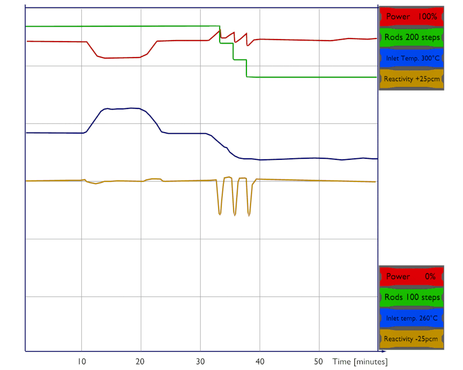
Let us assume that the reactor is critical at 75% of rated power and that the plant operator wants to increase power to 100% of rated power. The reactor operator must first bring the reactor supercritical by inserting a positive reactivity (e.g.,, by control rod withdrawal or boron dilution). As the thermal power increases, moderator temperature and fuel temperature increase, causing a negative reactivity effect (from the power coefficient), and the reactor returns to the critical condition. Positive reactivity must be continuously inserted (via control rods or chemical shim) to keep the power to be increasing. After each reactivity insertion, the reactor power stabilizes itself proportionately to the reactivity inserted. The total amount of feedback reactivity that must be offset by control rod withdrawal or boron dilution during the power increase (from ~1% – 100%) is known as the power defect.
Let assume:
- the power coefficient: Δρ/Δ% = -20pcm/% of rated power
- differential worth of control rods: Δρ/Δstep = 10pcm/step
- worth of boric acid: -11pcm/ppm
- desired trend of power decrease: 1% per minute
75% → ↑ 20 steps or ↓ 18 ppm of boric acid within 10 minutes → 85% → next ↑ 20 steps or ↓ 18 ppm within 10 minutes → 95% → final ↑ 10 steps or ↓ 9 ppm within 5 minutes → 100%
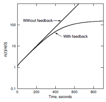
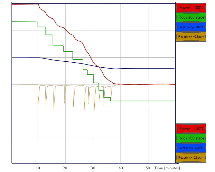
Let us assume that the reactor is critical at 100% of rated power and that the plant operator wants to decrease power to 75% of rated power. The reactor operator must first bring the reactor subcritical by inserting a negative reactivity (e.g.,, by control rod insertion or boric acid addition). As the thermal power decreases, moderator temperature and fuel temperature decrease, causing a positive reactivity effect (from the power coefficient), and the reactor returns to the critical condition. Negative reactivity must be continuously inserted (via control rods or chemical shim) to keep the power decreasing. After each reactivity insertion, the reactor power stabilizes itself proportionately to the reactivity inserted.
Let assume:
- the power coefficient: Δρ/Δ% = -20pcm/% of rated power
- differential worth of control rods: Δρ/Δstep = 10pcm/step
- worth of boric acid: -11pcm/ppm
- desired trend of power decrease: 1% per minute
100% → ↓ 20 steps or ↑ 18 ppm of boric acid within 10 minutes → 90%→ next ↓ 20 steps or ↑ 18 ppm within 10 minutes → 80% → final ↓ 10 steps or ↑ 9 ppm within 5 minutes→ 75%
Reactivity Coefficients
To describe the influence of all these processes on reactivity, one defines the reactivity coefficient α. A reactivity coefficient is defined as the change of reactivity per unit change in some operating parameter of the reactor. For example:
α = dρ⁄dT
The amount of reactivity, which is inserted into a reactor core by a specific change in an operating parameter, is usually known as the reactivity effect and is defined as:
dρ = α . dT
The reactivity coefficients that are important in power reactors (PWRs) are:
- Moderator Temperature Coefficient – MTC
- Fuel Temperature Coefficient or Doppler Coefficient
- Pressure Coefficient
- Void Coefficient
As can be seen, there are not only temperature coefficients that are defined in reactor dynamics. In addition to these coefficients, there are two other coefficients:
The total power coefficient is the combination of various effects and is commonly used when reactors are at power conditions. It is because, at power conditions, it is difficult to separate the moderator effect from the fuel effect and the void effect. All these coefficients will be described in the following separate sections. The reactivity coefficients are of importance in the safety of each nuclear power plant which is declared in the Safety Analysis Report (SAR).