2K Method – 3K Method
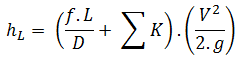
The K-value represents the multiple velocity heads that will be lost by the fluid passing through the fitting. The equation for calculation of pressure loss of the hydraulic element is, therefore:
 Therefore the equation for calculation of pressure loss of the entire hydraulic system is:
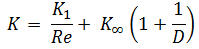
The K-value can be characterized for various flow regimes (i.e., according to the Reynolds number), and this causes it to be more accurate than the equivalent length method.
There are several other methods for calculating pressure loss for fittings, and these methods are more sophisticated and also more accurate:
- 2K-Method. The 2K method is a technique developed by Hooper B.W. to predict head loss in an elbow, valve, or tee. The 2K method improves the excess head method by characterizing the change in pressure loss due to varying Reynolds number. The 2-K method is advantageous over other methods, especially in the laminar flow region.
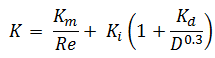
- 3K-Method. The 3K method (by Ron Darby in 1999) further improves the accuracy of the pressure loss calculation by also characterizing the change in geometric proportions of a fitting as its size changes. This makes the 3K method particularly accurate for a system with large fittings.

Summary:
- Head loss of the hydraulic system is divided into two main categories:
- Major Head Loss – due to friction in straight pipes
- Minor Head Loss – due to components as valves, bends…
- A special form of Darcy’s equation can be used to calculate minor losses.
- The minor losses are roughly proportional to the square of the flow rate, and therefore they can be easily integrated into the Darcy-Weisbach equation through resistance coefficient K.
- As a local pressure loss, fluid acceleration in a heated channel can also be considered.
There are the following methods:
- Equivalent length method
- K-method (resistance coeff. method)
- 2K-method
- 3K-method
Why is head loss very important?
As can be seen from the picture, the head loss is formed key characteristic of any hydraulic system. In systems in which some certain flowrate must be maintained (e.g.,, to provide sufficient cooling or heat transfer from a reactor core), the equilibrium of the head loss and the head added by a pump determine the flow rate through the system.
