The equivalent length method (The Le/D method) allows the user to describe the pressure loss through an elbow or a fitting as a length of straight pipe.
This method is based on the observation that the major losses are also proportional to the velocity head (v2/2g).

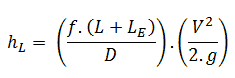
The Le/D method simply increases the multiplying factor in the Darcy-Weisbach equation (i.e., ƒ.L/D) by a length of straight pipe (i.e., Le) which would give rise to a pressure loss equivalent to the losses in the fittings, hence the name “equivalent length”. The multiplying factor, therefore, becomes ƒ(L+Le)/D and the equation for calculation of pressure loss of the system is, therefore:
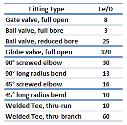
 All fittings, elbows, tees can be summed up to make one total length, and the pressure loss is calculated from this length. It has been experimentally found that if the equivalent lengths for a range of sizes of a given type of fitting are divided by the diameters of the fittings, then an almost constant ratio (i.e., Le/D) is obtained. The advantage of the equivalent length method is that a single data value is sufficient to cover all sizes of that fitting. Therefore the tabulation of equivalent length data is relatively easy. Some typical equivalent lengths are shown in the table.
See also: Pipe Sizing and Flow Calculation Software.
Summary:
- Head loss of the hydraulic system is divided into two main categories:
- Major Head Loss – due to friction in straight pipes
- Minor Head Loss – due to components as valves, bends…
- A special form of Darcy’s equation can be used to calculate minor losses.
- The minor losses are roughly proportional to the square of the flow rate, and therefore they can be easily integrated into the Darcy-Weisbach equation through resistance coefficient K.
- As a local pressure loss, fluid acceleration in a heated channel can also be considered.
There are the following methods:
- Equivalent length method
- K-method (resistance coeff. method)
- 2K-method
- 3K-method
Why is head loss very important?
As can be seen from the picture, the head loss is formed key characteristic of any hydraulic system. In systems in which some certain flowrate must be maintained (e.g.,, to provide sufficient cooling or heat transfer from a reactor core), the equilibrium of the head loss and the head added by a pump determine the flow rate through the system.
