According to 10 CFR Part 50; Criterion 11:
“The reactor core and associated coolant systems shall be designed so that in power operating range, the net effect of the prompt inherent nuclear feedback characteristics tends to compensate for a rapid increase in reactivity.”
At this point, we will discuss the reactor stability at power operation. The neutron population is always large enough to generate heat at power operation. The main purpose of power reactors is to generate a large amount of heat, and this causes the temperature of the system to change, and material densities change as well (due to the thermal expansion).

These changes in reactivity are usually called reactivity feedbacks and are characterized by reactivity coefficients. The reactivity feedbacks and their time constants are a very important area of reactor design because they determine the stability of the reactor.
In the previous article (Point Dynamics Equations), we have assumed a simplified feedback equation:
![]()
This equation expresses the dependence of the reactivity on various parameters. But in this case, there is a dependence on the coolant and the fuel temperature only. For PWRs, temperature stability is important in overall stability because most instabilities arise from temperature instability. For illustration, we will use a further simplified model, which assumes that there is only one temperature coefficient for fuel and moderator:
The response of a reactor to a change in temperature (i.e., the overall reactor stability) depends especially on the algebraic sign of αT. A reactor with negative αT is inherently stable to changes in its temperature and thermal power, while a reactor with positive αT is inherently unstable. We will demonstrate the problem in the following two examples.
Positive reactivity feedback – αT > 0
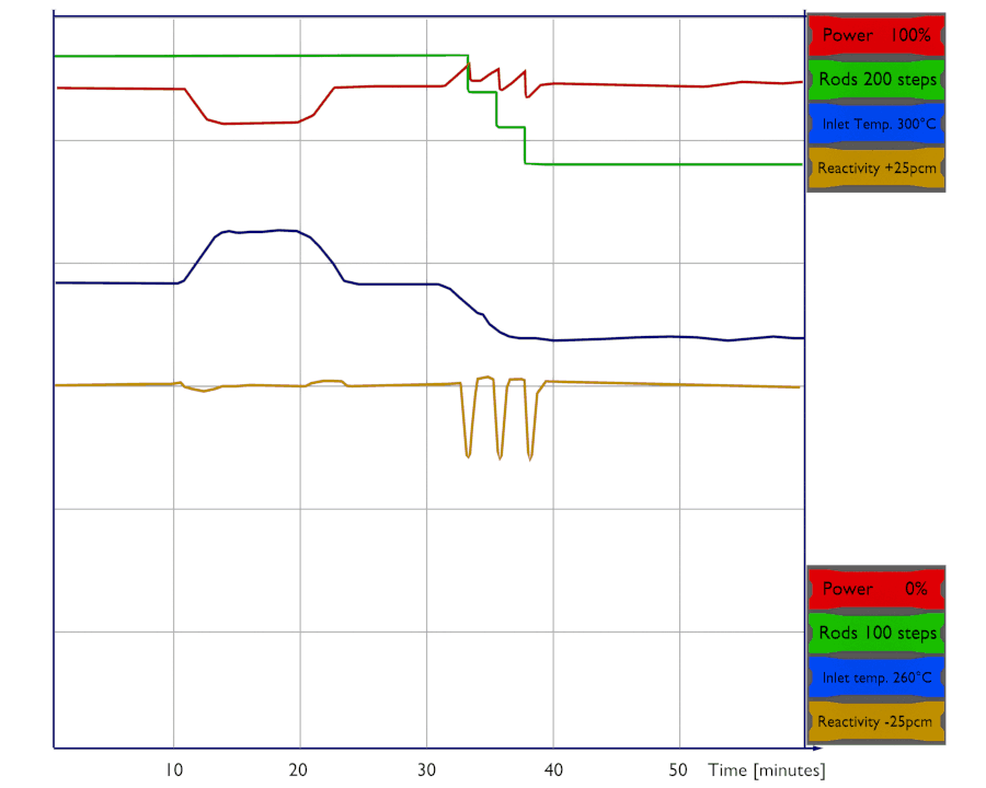
Assume αT > 0 (temperature coefficient for fuel and moderator). If the temperature of the moderator is increased, positive reactivity is added to the core. This positive reactivity causes reactor power to further increase, which acts in the same direction as initial reactivity addition. Without compensation, the reactivity of the system would increase, and the thermal power would accelerate and increase as well (see figure).
On the other hand, as the thermal power decreases, the reactor temperature decreases, giving a further decrease in reactivity. This feedback would accelerate the initial decrease in thermal power, and the reactor would shut down itself. In any case, the reactor power does not stabilize itself.
Negative reactivity feedback – αT < 0
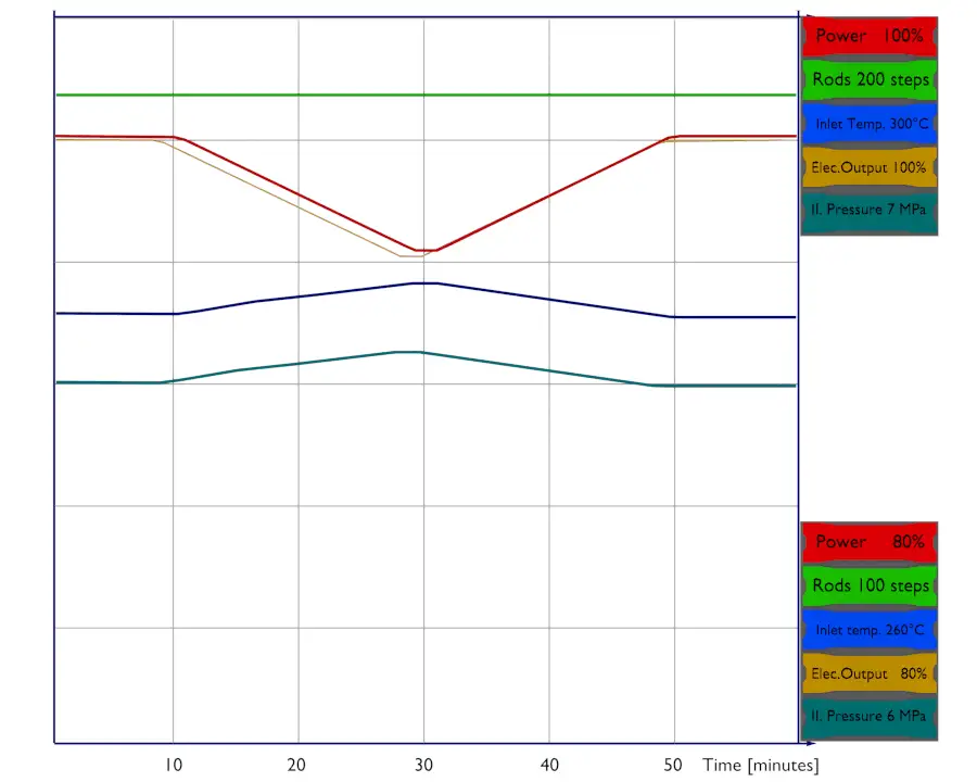
The above situation is quite different when αT < 0. In this case, if the temperature of the moderator is increased, negative reactivity is added to the core. This negative reactivity causes reactor power to decrease, which acts against any further increase in temperature or power. As the thermal power decreases, the power coefficient (which is also based on the sign of αT) acts against this decrease, and the reactor returns to the critical condition (steady-state). The reactor power stabilizes itself. This effect is shown in the picture. Let’s assume all the changes are initiated by the changes in the core inlet temperature.
At this point, it must be noted that the temperature does not change uniformly throughout a reactor core. An increase in thermal power, for example, is reflected first by an increase in the temperature of the fuel since this is the region where most of the thermal power is generated. The coolant temperature and, in thermal reactors, the moderator temperature does not change until the heat has been transferred from the fuel to the reactor coolant. The time for heat to be transferred to the moderator is usually measured in seconds (~5s).
Therefore it is necessary to specify the component whose temperature changes:
 As was written, the moderator temperature coefficient is primarily a function of the moderator-to-fuel ratio (NH2O/NFuel ratio). The moderator-to-fuel ratio is the ratio of the number of moderator nuclei within the volume of a reactor core to the number of fuel nuclei. As the core temperature increases, fuel volume and number density remain essentially constant. The volume of moderator also remains constant, but the number density of moderator decreases with thermal expansion. As the moderator temperature increases, the ratio of the moderating atoms (molecules of water) decreases due to the thermal expansion of water (especially at 300°C; see: Density of Water). Its density simply and significantly decreases. This, in turn, causes hardening of neutron spectrum in the reactor core resulting in higher resonance absorption (lower p). The decreasing density of the moderator causes neutrons to stay at a higher energy for a longer period, which increases the probability of non-fission capture of these neutrons. This process is one of three processes that determine the moderator temperature coefficient (MTC). The second process is associated with the leakage probability of the neutrons and the third with the thermal utilization factor.
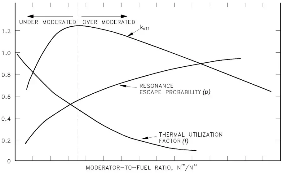
The moderator-to-fuel ratio strongly influences especially:
- Resonance escape probability. An increase in the moderator-to-fuel ratio causes an increase in resonance escape probability. As more moderator molecules are added relative to the number of fuel molecules, then it becomes easy for neutrons to slow down to thermal energies without encountering a resonance absorption at the resonance energies.
- Thermal utilization factor. An increase in the moderator-to-fuel ratio causes a decrease in the thermal utilization factor. The value of the thermal utilization factor is given by the ratio of the number of thermal neutrons absorbed in the fuel (all nuclides) to the number of thermal neutrons absorbed in all the material that makes up the core.
- Thermal and fast non-leakage probability. An increase in moderator-to-fuel ratio causes a decrease in migration length, which in turn causes an increase in non-leakage probability.
As can be seen from the figure, at low moderator-to-fuel ratios, the product of all the six factors (keff) is small because the resonance escape probability is small. At the optimal value of the moderator-to-fuel ratio, keff reaches its maximum value, which is the case of so-called “optimal moderation”. At large ratios, keff is again small because the thermal utilization factor is small.
Under-moderated vs. Over-moderated Reactor
From the moderator-to-fuel ratio point of view, any multiplying system can be designed as:
- Under-moderated. Under-moderation means less than the optimum amount of moderator between fuel plates or fuel rods. An increase in moderator temperature and voids decreases the keff of the system and inserts negative reactivity. An under-moderated core would create a negative temperature and void feedback required for a stable system.
- Over-moderated. Over-moderation means a higher than optimum amount of moderator between fuel plates or fuel rods. An increase in moderator temperature and voids increases the keff of the system and inserts positive reactivity. An over-moderated core would create a positive temperature and void feedback. It will result in an unstable system unless another negative feedback mechanism (e.g., the Doppler broadening) overrides the positive effect.
Reactor engineers must balance the composite effects of moderator density, fuel temperature, and other phenomena to ensure system stability under all operating conditions. Most light water reactors are therefore designed as so-called under-moderated, and the neutron flux spectrum is slightly harder (the moderation is slightly insufficient) than in an optimum case. But this design provides an important safety feature. An increase in the moderator temperature results in negative reactivity, which tends to make the reactor self-regulating. It must be added the overall feedback must be negative. Still, local positive coefficients exist in areas with large water gaps that are over-moderated such as near control rods guide tubes.
Another phenomenon associated with an under-moderated core is called the neutron flux trap effect. This effect causes an increase in local power generation due to better thermalization of neutrons in areas with large water gaps (between fuel assemblies or when the fuel assembly bow phenomenon is present). Note that “flux traps” are a standard feature of most modern test reactors because of the desire to obtain high thermal neutron fluxes for the irradiation of materials. Still, it can also occur in PWRs.
On the other hand, also under-moderation has its limits. In general, it causes a decrease in overall keff; therefore, more fissile material is needed to ensure the criticality of the core. Moreover, there is also a limit on the minimal value of MTC (most negative). It is because the negative temperature feedback also acts against the decrease in the moderator temperature. Consider what happens when moderator temperature is decreased quickly, as in the case of the main steamline break (MSLB – standard initiating event for PWRs). The steamline break causes the steam pressure the saturation temperature in the steam generators to fall rapidly. As a result of the falling saturation temperature in the steam generators, the moderator temperature will rapidly decrease. The rapid moderator temperature drop causes a positive reactivity insertion. The amount of reactivity inserted also depends on the magnitude of the MTC, and therefore it must be limited. The typical value for the lower limit is MTC = -80 pcm/°C, but it is a plant-specific value limited in technical specifications.
Examples: Reactor Stability
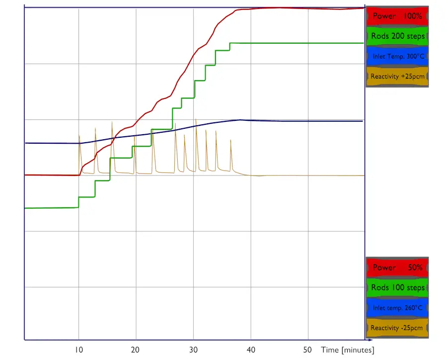
Let’s assume that the reactor is critical at 75% of rated power and that the plant operator wants to increase power to 100% of rated power. The reactor operator must first bring the reactor supercritical by inserting a positive reactivity (e.g., by control rod withdrawal or boron dilution). As the thermal power increases, moderator temperature and fuel temperature increase, causing a negative reactivity effect (from the power coefficient), and the reactor returns to the critical condition. Positive reactivity must be continuously inserted (via control rods or chemical shim) to keep the power increasing. After each reactivity insertion, the reactor power stabilizes itself proportionately to the reactivity inserted. The total amount of feedback reactivity that must be offset by control rod withdrawal or boron dilution during the power increase (from ~1% – 100%) is known as the power defect.
Let assume:
- the power coefficient: Δρ/Δ% = -20pcm/% of rated power
- differential worth of control rods: Δρ/Δstep = 10pcm/step
- worth of boric acid: -11pcm/ppm
- desired trend of power decrease: 1% per minute
75% → ↑ 20 steps or ↓ 18 ppm of boric acid within 10 minutes → 85% → next ↑ 20 steps or ↓ 18 ppm within 10 minutes → 95% → final ↑ 10 steps or ↓ 9 ppm within 5 minutes → 100%
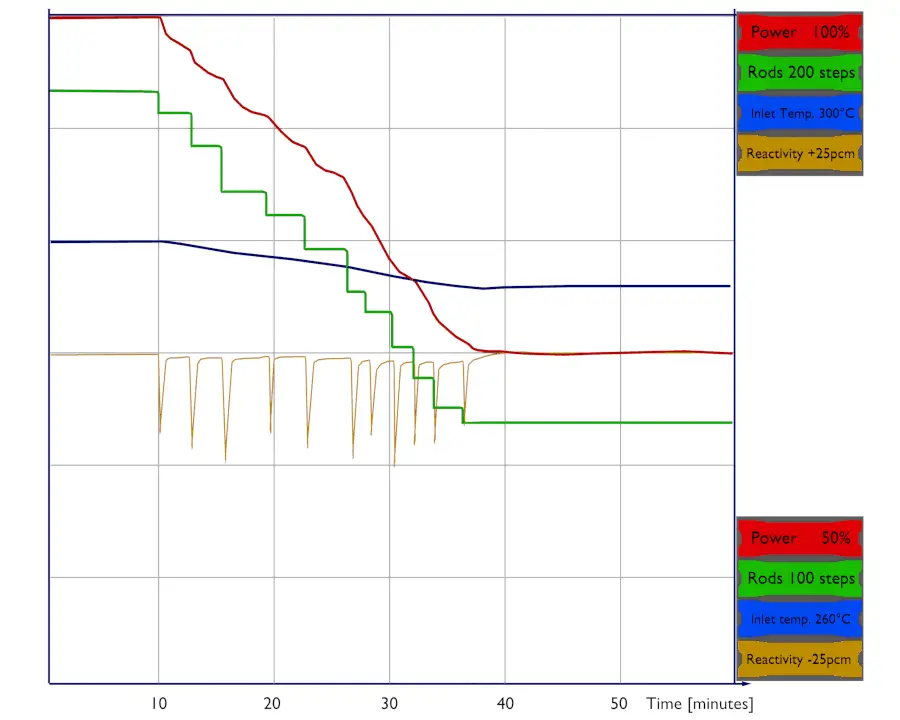
Let’s assume that the reactor is critical at 100% of rated power and that the plant operator wants to decrease power to 75% of rated power. The reactor operator must first bring the reactor subcritical by inserting a negative reactivity (e.g., by control rod insertion or boric acid addition). As the thermal power decreases, moderator temperature and fuel temperature decrease, causing a positive reactivity effect (from the power coefficient), and the reactor returns to the critical condition. Negative reactivity must be continuously inserted (via control rods or chemical shim) to keep the power decreasing. After each reactivity insertion, the reactor power stabilizes itself proportionately to the reactivity inserted.
Let assume:
- the power coefficient: Δρ/Δ% = -20pcm/% of rated power
- differential worth of control rods: Δρ/Δstep = 10pcm/step
- worth of boric acid: -11pcm/ppm
- desired trend of power decrease: 1% per minute
100% → ↓ 20 steps or ↑ 18 ppm of boric acid within 10 minutes → 90%→ next ↓ 20 steps or ↑ 18 ppm within 10 minutes → 80% → final ↓ 10 steps or ↑ 9 ppm within 5 minutes→ 75%
Flow Instabilities in BWRs
Coupled Neutronic-Thermohydraulic Instability
See also: Flow Instability
The dominant type of instabilities in commercial BWRs is the coupled neutronic-thermohydraulic instability (also known as reactivity instability). The power generation in BWRs is directly related to the fuel neutron flux, which is strongly related to the average void fraction in the core channels. This effect is known as reactivity feedback. The reactivity feedback caused by changes in void fraction (void coefficient) is delayed as the voids travel upward through the fuel channel. In some cases, the delay may be long enough, and the void feedback may be strong enough that the reactor configuration becomes unstable. In this case, the neutron flux may oscillate.