In short, effective shielding of gamma radiation is in most cases based on the use of materials with two following material properties:
- high-density of material
- the high atomic number of material (high Z materials)
However, low-density materials and low Z materials can be compensated with increased thickness, which is as significant as density and atomic number in shielding applications.
A lead is widely used as a gamma shield. The major advantage of the lead shield is its compactness due to its higher density. On the other hand, depleted uranium is much more effective due to its higher Z. Depleted uranium shields in portable gamma-ray sources.
In nuclear power plants, shielding of a reactor core can be provided by materials of reactor pressure vessel, reactor internals (neutron reflector). Also, heavy concrete is usually used to shield both neutrons and gamma radiation.
Although water is neither high density nor high Z material, it is commonly used as gamma shields. Water provides a radiation shielding of fuel assemblies in a spent fuel pool during storage or transports from and into the reactor core.
In general, gamma radiation shielding is more complex and difficult than alpha or beta radiation shielding. To comprehensively understand how a gamma-ray loses its initial energy, how it can be attenuated, and how it can be shielded, we must have detailed knowledge of its interaction mechanisms.
See also more theory: Interaction of Gamma Radiation with Matter
See also calculator: Gamma activity to dose rate (with/without shield)
See also XCOM – photon cross-section DB: XCOM: Photon Cross Sections Database
Characteristics of Gamma Rays / Radiation
Key features of gamma rays are summarized in the following few points:
-
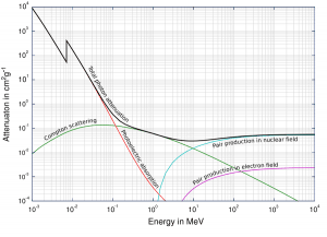
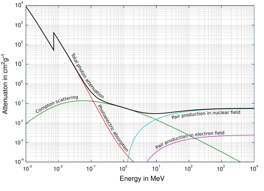
Total photon cross-sections.
Source: Wikimedia CommonsGamma rays are high-energy photons (about 10 000 times as much energy as the visible photons), the same photons as the photons forming the visible range of the electromagnetic spectrum – light.
- Photons (gamma rays and X-rays) can ionize atoms directly (despite they are electrically neutral) through the Photoelectric effect and the Compton effect, but secondary (indirect) ionization is much more significant.
- Gamma rays ionize matter primarily via indirect ionization.
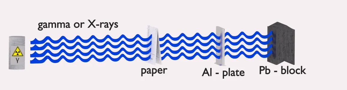
- Although many possible interactions are known, there are three key interaction mechanisms with the matter.
- Gamma rays travel at the speed of light, and they can travel thousands of meters in the air before spending their energy.
- Since gamma radiation is very penetrating, it must be shielded by very dense materials, such as lead or uranium.
- The distinction between X-rays and gamma rays is not so simple and has changed in recent decades. According to the currently valid definition, X-rays are emitted by electrons outside the nucleus, while the nucleus emits gamma rays.
- Gamma rays frequently accompany the emission of alpha and beta radiation.
Gamma Rays Attenuetion
The total cross-section of the interaction of gamma rays with an atom is equal to the sum of all three mentioned partial cross-sections:σ = σf + σC + σp
- σf – Photoelectric effect
- σC – Compton scattering
- σp – Pair production
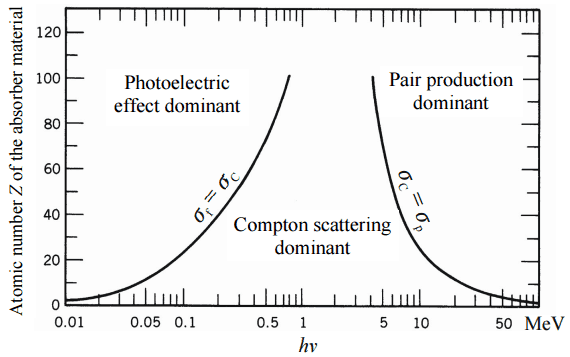
One of the three partial cross-sections may become much larger than the other two depending on the gamma-ray energy and the absorber material. At small values of gamma-ray energy, the photoelectric effect dominates. Compton scattering dominates at intermediate energies. The Compton scattering also increases with decreasing atomic number of matter. Therefore the interval of domination is wider for light nuclei. Finally, electron-positron pair production dominates at high energies.
Based on the definition of interaction cross-section, the dependence of gamma rays intensity on the thickness of absorber material can be derived. If monoenergetic gamma rays are collimated into a narrow beam and if the detector behind the material only detects the gamma rays that passed through that material without any interaction, then the dependence should be simple exponential attenuation gamma rays. Each interaction removes the photon from the beam either by absorption or scattering away from the detector direction. Therefore the interactions can be characterized by a fixed probability of occurrence per unit path length in the absorber. The sum of these probabilities is called the linear attenuation coefficient:
μ = τ(photoelectric) + σ(Compton) + κ(pair)
Linear Attenuation Coefficient
The following equation can then describe the attenuation of gamma radiation.
I=I0.e-μx
where I is intensity after attenuation, Io is incident intensity, μ is the linear attenuation coefficient (cm-1), and the physical thickness of absorber (cm).

The materials listed in the table beside are air, water, and different elements from carbon (Z=6) to lead (Z=82). Their linear attenuation coefficients are given for three gamma-ray energies. There are two main features of the linear attenuation coefficient:
- The linear attenuation coefficient increases as the atomic number of the absorber increases.
- The linear attenuation coefficient for all materials decreases with the energy of the gamma rays.
Half Value Layer
The half-value layer expresses the thickness of absorbing material needed to reduce the incident radiation intensity by a factor of two. There are two main features of the half-value layer:
- The half-value layer decreases as the atomic number of the absorber increases. For example, 35 m of air is needed to reduce the intensity of a 100 keV gamma-ray beam by a factor of two, whereas just 0.12 mm of lead can do the same thing.
- The half-value layer for all materials increases with the energy of the gamma rays. For example, from 0.26 cm for iron at 100 keV to about 1.06 cm at 500 keV.
Example
How much water shielding do you require if you want to reduce the intensity of a 500 keV monoenergetic gamma-ray beam (narrow beam) to 1% of its incident intensity? The half-value layer for 500 keV gamma rays in water is 7.15 cm, and the linear attenuation coefficient for 500 keV gamma rays in water is 0.097 cm-1. The question is quite simple and can be described by the following equation:If the half-value layer for water is 7.15 cm, the linear attenuation coefficient is:
Now we can use the exponential attenuation equation:
therefore
So the required thickness of water is about 47.5 cm. This is a relatively large thickness, and it is caused by small atomic numbers of hydrogen and oxygen. If we calculate the same problem for lead (Pb), we obtain the thickness x=2.8cm.
Linear Attenuation Coefficients
Table of Linear Attenuation Coefficients (in cm-1) for different materials at gamma-ray energies of 100, 200, and 500 keV.
| Absorber | 100 keV | 200 keV | 500 keV |
| Air | 0.0195/m | 0.0159/m | 0.0112/m |
| Water | 0.167/cm | 0.136/cm | 0.097/cm |
| Carbon | 0.335/cm | 0.274/cm | 0.196/cm |
| Aluminium | 0.435/cm | 0.324/cm | 0.227/cm |
| Iron | 2.72/cm | 1.09/cm | 0.655/cm |
| Copper | 3.8/cm | 1.309/cm | 0.73/cm |
| Lead | 59.7/cm | 10.15/cm | 1.64/cm |
Half Value Layers
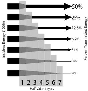
The half-value layer expresses the thickness of absorbing material needed to reduce the incident radiation intensity by a factor of two. With a half-value layer, it is easy to perform simple calculations.
Source: www.nde-ed.org
Table of Half Value Layers (in cm) for different materials at gamma-ray energies of 100, 200, and 500 keV.
| Absorber | 100 keV | 200 keV | 500 keV |
| Air | 3555 cm | 4359 cm | 6189 cm |
| Water | 4.15 cm | 5.1 cm | 7.15 cm |
| Carbon | 2.07 cm | 2.53 cm | 3.54 cm |
| Aluminium | 1.59 cm | 2.14 cm | 3.05 cm |
| Iron | 0.26 cm | 0.64 cm | 1.06 cm |
| Copper | 0.18 cm | 0.53 cm | 0.95 cm |
| Lead | 0.012 cm | 0.068 cm | 0.42 cm |
Mass Attenuation Coefficient
When characterizing an absorbing material, we can sometimes use the mass attenuation coefficient. The mass attenuation coefficient is defined as the ratio of the linear attenuation coefficient and absorber density (μ/ρ). The following equation can then describe the attenuation of gamma radiation:
I=I0.e-(μ/ρ).ρl
, where ρ is the material density, (μ/ρ) is the mass attenuation coefficient, and ρ.l is the mass thickness. The measurement unit was used for the mass attenuation coefficient cm2g-1.
For intermediate energies, the Compton scattering dominates, and different absorbers have approximately equal mass attenuation coefficients. This is because the cross-section of Compton scattering is proportional to the Z (atomic number), and therefore the coefficient is proportional to the material density ρ. At small gamma-ray energy values or high gamma-ray energy values, the coefficient is proportional to higher powers of the atomic number Z (for photoelectric effect σf ~ Z5; for pair production σp ~ Z2), the attenuation coefficient μ is not a constant.
Validity of Exponential Law
The exponential law will always describe the attenuation of the primary radiation by matter. If secondary particles are produced, or the primary radiation changes its energy or direction, the effective attenuation will be much less. The radiation will penetrate more deeply into matter than is predicted by the exponential law alone. The process must be taken into account when evaluating the effect of radiation shielding.

Calculation of Shielded Dose Rate in Sieverts from Contaminated Surface
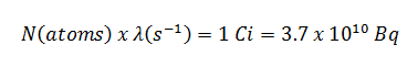
Assume a surface in which 1.0 Ci of 137Cs contaminates. Assume that this contaminant can be approximated by the point isotropic source, which contains 1.0 Ci of 137Cs, with a half-life of 30.2 years. Note that the relationship between half-life and the amount of a radionuclide required to give an activity of one curie is shown below. This amount of material can be calculated using λ, which is the decay constant of certain nuclide:
About 94.6 percent decays by beta emission to a metastable nuclear isomer of barium: barium-137m. The main photon peak of Ba-137m is 662 keV. For this calculation, assume that all decays go through this channel.
Calculate the primary photon dose rate, in sieverts per hour (Sv.h-1), at the outer surface of a 5 cm thick lead shield. Then calculate the equivalent and effective dose rates for two cases.
- Assume that this external radiation field penetrates uniformly through the whole body. That means: Calculate the effective whole-body dose rate.
- Assume that this external radiation field penetrates only lungs, and the other organs are completely shielded. That means: Calculate the effective dose rate.
Note that, primary photon dose rate neglects all secondary particles. Assume that the effective distance of the source from the dose point is 10 cm. We shall also assume that the dose point is soft tissue and can reasonably be simulated by water, and we use the mass-energy absorption coefficient for water.
See also: Gamma Ray Attenuation
See also: Shielding of Gamma Rays
Solution:
The primary photon dose rate is attenuated exponentially, and the dose rate from primary photons, taking account of the shield, is given by:
As can be seen, we do not account for the buildup of secondary radiation. If secondary particles are produced, or the primary radiation changes its energy or direction, the effective attenuation will be much less. This assumption generally underestimates the true dose rate, especially for thick shields and when the dose point is close to the shield surface, but this assumption simplifies all calculations. For this case, the true dose rate (with the buildup of secondary radiation) will be more than two times higher.
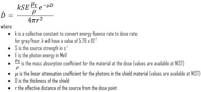
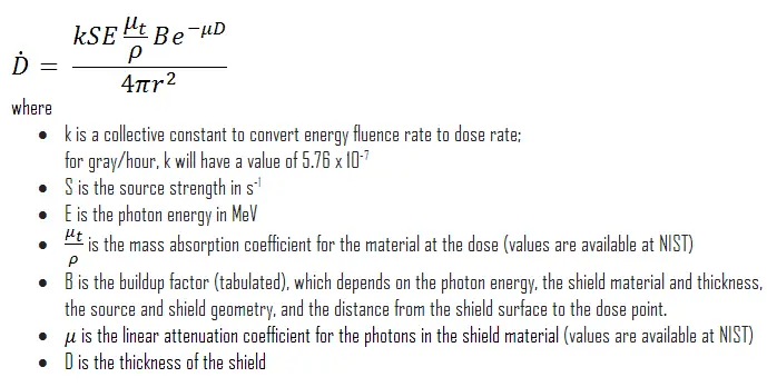
To calculate the absorbed dose rate, we have to use the formula:
- k = 5.76 x 10⁻⁷
- S = 3.7 x 10¹⁰ s-1
- E = 0.662 MeV
- μt/ρ = 0.0326 cm2/g (values are available at NIST)
- μ = 1.289 cm-1 (values are available at NIST)
- D = 5 cm
- r = 10 cm
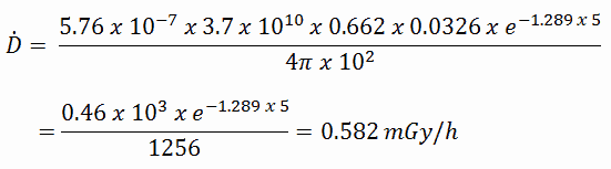
Result:
The resulting absorbed dose rate in grays per hour is then:
1) Uniform irradiation
Since the radiation weighting factor for gamma rays is equal to one, and we have assumed the uniform radiation field (the tissue weighting factor is also equal to unity), we can directly calculate the equivalent dose rate and the effective dose rate (E = HT) from the absorbed dose rate as:
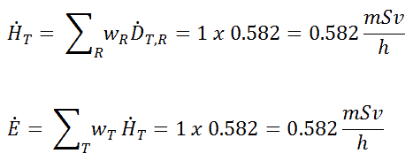
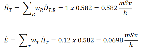
2) Partial irradiation
In this case, we assume partial irradiation of lungs only. Thus, we have to use the tissue weighting factor, which is equal to wT = 0.12. The radiation weighting factor for gamma rays is equal to one. As a result, we can calculate the effective dose rate as:
Note that if one part of the body (e.g.,, the lungs) receives a radiation dose, it represents a risk for a particularly damaging effect (e.g.,, lung cancer). If the same dose is given to another organ, it represents a different risk factor.
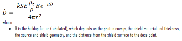
If we want to account for the buildup of secondary radiation, then we have to include the buildup factor. The extended formula for the dose rate is then:
Buildup Factors for Gamma Rays Shielding
The buildup factor is a correction factor that considers the influence of the scattered radiation plus any secondary particles in the medium during shielding calculations. If we want to account for the buildup of secondary radiation, then we have to include the buildup factor. The buildup factor is then a multiplicative factor that accounts for the response to the un-collided photons to include the contribution of the scattered photons. Thus, the buildup factor can be obtained as a ratio of the total dose to the response for un-collided dose.
The extended formula for the dose rate calculation is:
The ANSI/ANS-6.4.3-1991 Gamma-Ray Attenuation Coefficients and Buildup Factors for Engineering Materials Standard, contains derived gamma-ray attenuation coefficients and buildup factors for selected engineering materials and elements for use in shielding calculations (ANSI/ANS-6.1.1, 1991).