 In the volute of the pump fluid enters the pump axially through the eye of the impeller (low pressure area) which rotates at high speed. As the impeller and blades rotate, they transfer momentum to incoming fluid. The fluid accelerates radially outward from the pump chasing, and a vacuum is created at the impeller’s eye that continuously draws more fluid into the pump. As the fluid’s velocity increases, its kinetic energy increases. A fluid of high kinetic energy is forced out of the impeller area and enters the volute. The fluid flows through a continuously increasing cross-sectional area in the volute, where the kinetic energy is converted into fluid pressure (according to Bernoulli’s principle).
The impeller blades are usually backward-curved, but there are also radial and forward-curved blade designs. The output pressure slightly changes according to the design used. The blades may be open or closed. Also, the diffuser may be fitted with fixed vanes to help guide the flow toward the exit. The energy transferred to the liquid corresponds to the velocity at the edge of the impeller. The faster the impeller revolves or, the bigger the impeller is, the higher will the velocity head be.
Cavitation in Centrifugal Pumps
 Major places where cavitation occurs are in pumps, on impellers, or propellers. In centrifugal pumps, cavitation results from a reduction in suction pressure, an increase in suction temperature, or an increase in the flow rate above that the pump has been designed.
There are two basic types of pump cavitation:
Suction Cavitation
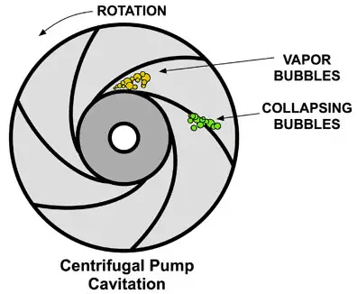 Suction cavitation, or classic cavitation, occurs when a pump is under low pressure or high vacuum conditions. When the liquid being pumped enters the eye of a centrifugal pump, the pressure is significantly reduced. In some cases, the pressure drop is great enough to cause the liquid to flash to steam when the local pressure falls below the saturation pressure for the fluid that is being pumped. Bubbles or cavities will form at the eye of the impeller, and subsequently, the formed vapor bubbles move into regions of higher pressure as they travel towards the pump discharge. In the higher pressure region, the vapor bubbles collapse suddenly on the outer portions of the impeller. This can cause significant damage to all moving parts of a centrifugal pump.
Typical causes of suction cavitation:
- The pump is running too far right on the pump curve
- Poor suction conditions (NPSH requirements)
- Blockage in the pipe on the suction side
- Inappropriate piping design
- Clogged filters or strainers
To prevent this type of cavitation, the Net Positive Suction Head Available (NPSHa) in the system must be higher than the required NPSH of the pump. This problem is typical for suction cavitation, and therefore this type of cavitation is also called inadequate NPSHa cavitation.
Besides the change of the pump, problems with suction cavitation can also be solved by:
- Lowering the temperature
- Reduction of motor RPM if possible
- Increase in the diameter of the eye of the impeller
- Use of an impeller inducer.
- Use of two parallel pumps with lower capacity.
- Use of a booster pump to feed the principal pump.
Special case of cavitation occurs at the suction side as a result of inappropriate piping in suction line. Use of restrictions, sharp elbows and other hydraulic equipment can turbulize the flow this can contribute to cavitation formation.
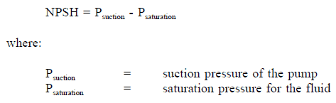
Net Positive Suction Head or NPSH for pumps can be defined as the difference between the suction pressure and the saturation pressure of the fluid, expressed in terms of the height of the liquid column. NPSH is used to measure how close a fluid is to saturated conditions. Lowering the pressure at the suction side can induce cavitation. If cavitation occurs, the violent collapse of the cavitation bubble creates a shock wave that can carve material from internal pump components (usually the leading edge of the impeller) and creates noise often described as “pumping gravel”. Additionally, the inevitable increase in vibration can cause other mechanical faults in the pump and associated equipment.
In general, there are two suction heads defined in hydraulics:
- NPSH Available (NPSHa): The absolute pressure at the suction port of the pump. NPSHa is a function of water temperature. As the inlet temperature increases, NPSHa decreases because the saturation pressure decreases.
- NPSH Required (NPSHR): The minimum pressure required at the pump’s suction port to keep the pump from cavitating. NPSHa is not a function of water temperature.
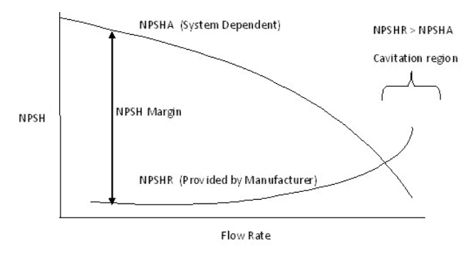
NPSHA is a function of your system and must be calculated, whereas NPSHR is a pump function and must be provided by the pump manufacturer. During operation, the available NPSH must be maintained at a level greater than the NPSH required by the pump manufacturer. It has been found that cavitation rates increase rapidly with the increase in the volume flow rate. This can be seen from the picture. As the volume flow rate increases, NPSH required increases, but the available NPSH decreases.
How to increase NPSH available?
To avoid suction cavitation, NPSH available must be increased as much as possible. The only way to increase NPSH available is to increase the pressure at the pump inlet:
- Lower the pump level
- Raise the reservoir level
- Reduction of motor RPM if possible
- Reduce minor losses upstream of the pump
- Reduce major losses upstream of the pump
- Shorten the length of the pipe
- Use a smoother pipe
- Increase in the diameter of the eye of the impeller
- Use of a booster pump to feed the principal pump.
Discharge Cavitation
 Discharge cavitation occurs when the pump discharge pressure is extremely high or when the discharge flow is restricted and cannot leave the pump (e.g.,, caused by a closed outlet valve). An extremely high discharge pressure results in the majority of the pumped fluid circulating inside the pump.
This type of cavitation originates from two sources. First, this internal circulation (from high-pressure zones into low-pressure zones) is forced through the clearance between the impeller and the pump housing at high velocity resulting in the formation of a low-pressure region (as a result of Bernoulli’s principle) in which cavitation can occur. Second, the liquid is circulating inside the volute of the pump, and it rapidly overheats.
In both cases, cavitation has similar consequences. The implosion of bubbles triggers intense shockwaves, causing premature wear of the impeller tips and pump housing. In an extreme case, discharge cavitation can cause the impeller shaft to break.
Typical causes of discharge cavitation:
- Pump is running too far left on the pump curve
- Blockage in the pipe on discharge side
- Clogged filters or strainers
- Inappropriate piping design
Cavitation Number
The Cavitation Number (Ca) or Cavitation Parameter is a dimensionless number used in flow calculations. It is conventional to characterize how close the pressure in the liquid flow is to the vapor pressure (and therefore the potential for cavitation) by means of the cavitation number.
The Cavitation Number can be expressed as:

where
CA = Cavitation Number
p = local pressure (Pa)
pv = vapor pressure of the fluid (Pa)
ρ = density of the fluid (kg/m3)
v = velocity of fluid (m/s)
Cavitation Damage
Cavitation is, in many cases, an undesirable occurrence. In centrifugal pumps, cavitation causes damage to components (erosion of the material), vibrations, noise, and a loss of efficiency.
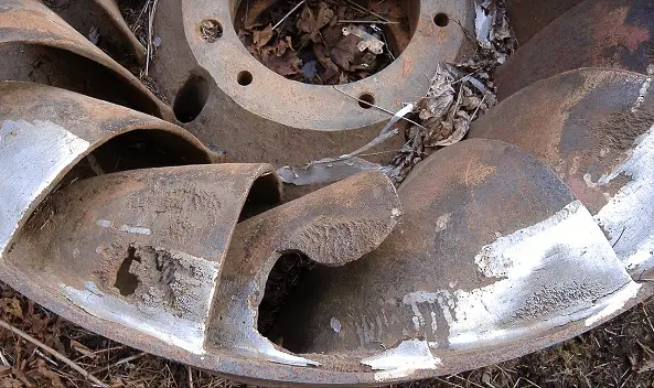
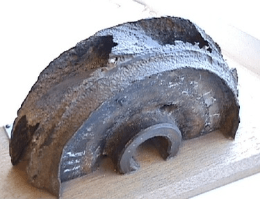
https://commons.wikimedia.org/wiki/File:Turbine_Francis_Worn.JPG
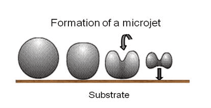
Perhaps the most important engineering problem caused by cavitation is the material damage that cavitation bubbles can cause when they collapse in the vicinity of a solid surface. Cavitation bubbles collapse is a violent process that generates highly localized shock waves and microjets. They force energetic liquid into very small volumes, thereby creating high-temperature spots, and these intense disturbances generate highly localized and transient surface stresses to a solid surface. Signs of erosion will appear as pitting due to the water hammering action of the collapsing vapor bubbles. It has been found that cavitation damage rates increase rapidly with the increase in the volume flow rate.
Softer materials can be damaged even by the short-term occurrence of cavitation. Individual pits can be observed after a single bubble collapse. Therefore harder materials are used for centrifugal pumps. But with the harder materials used in most applications, the cyclic stress due to repeated collapses can cause local surface fatigue failure. Thus cavitation damage to metals usually has the appearance of fatigue failure.
 When the cavitation bubbles collapse, they force energetic liquid into very small volumes, thereby creating spots of high temperature and emitting shock waves, the latter of which are a source of the noise. Although the collapse of a small cavity is a relatively low-energy event, highly localized collapses can erode metals, such as steel, over time. The pitting caused by the collapse of cavities produces great to wear on components and can dramatically shorten a propeller or pump’s lifetime.
Cavitation is usually accompanied also by:
- Noise. Typical noise is caused by collapsing cavities. The level of noise that results from cavitation is a measure of the severity of the cavitation.
- Vibration. Pump vibrations due to cavitation are characteristically low-frequency vibrations, usually found in the 0 to 10 Hz range.
- Reduction in pump efficiency. A decrease in the efficiency of the pump is a more reliable sign of cavitation occurring.