Zirconium Alloy
A typical composition of nuclear-grade zirconium alloys is more than 95 weight percent zirconium and less than 2% of tin, niobium, iron, chromium, nickel, and other metals added to improve mechanical properties and corrosion resistance. To date, the most commonly used alloy in PWRs has been Zircaloy 4. However, currently, this is being replaced by new zirconium–niobium-based alloys, exhibiting better corrosion resistance. The maximum temperature at which zirconium alloys can be used in water-cooled reactors depends on their corrosion resistance. Alloys of type Zircalloy, in which tin is the basic alloying element that improves their mechanical properties, have a wide distribution worldwide. However, in this case, the decrease of corrosion resistance in water and steam is taken place, resulting in the need for additional alloying. The improvement brought about by the additive niobium probably involves a different mechanism. The high corrosion resistance of niobium alloyed metals in water and steam at temperatures of 400–550°C is caused by their ability to passivation with the formation of protective films.
See also: Zirconium
 Zirconium is a lustrous, grey-white, strong transition metal that resembles hafnium and titanium to a lesser extent. Zirconium is mainly used as a refractory and opacifier, although small amounts are used as an alloying agent for its strong corrosion resistance. Zirconium alloy (e.g., Zr + 1%Nb) is widely used as a cladding for nuclear reactor fuels. The desired properties of these alloys are a low neutron-capture cross-section and resistance to corrosion under normal service conditions. Commercial non-nuclear grade zirconium typically contains 1–5% of hafnium, whose neutron absorption cross-section is 600x that of zirconium. Hafnium must be almost entirely removed (reduced to < 0.02% of the alloy) for reactor applications. Zirconium alloys have lower thermal conductivity (about 18 W/m.K) than pure zirconium metal (about 22 W/m.K).
Temperature Profile – Fuel Pellets
See also: Temperature Profile – Calculation
See also: Cladding Surface Temperature
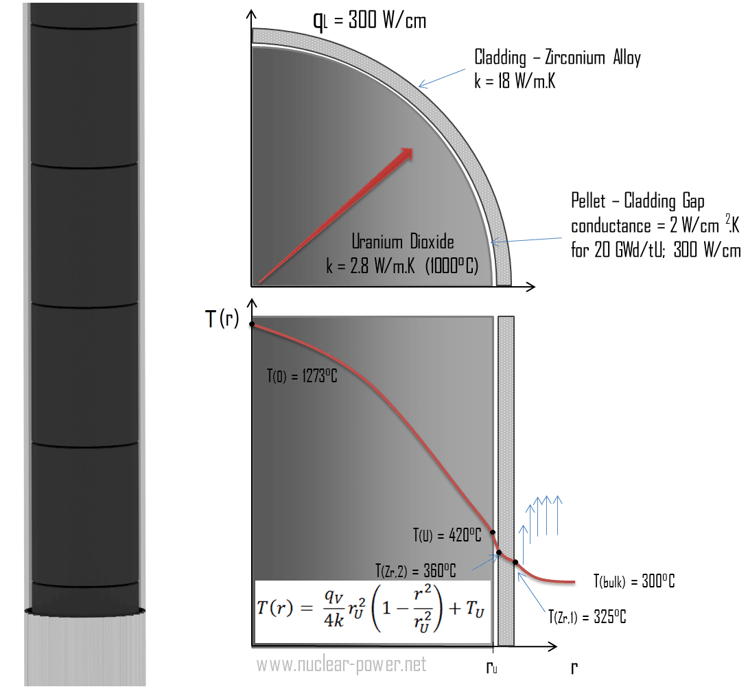
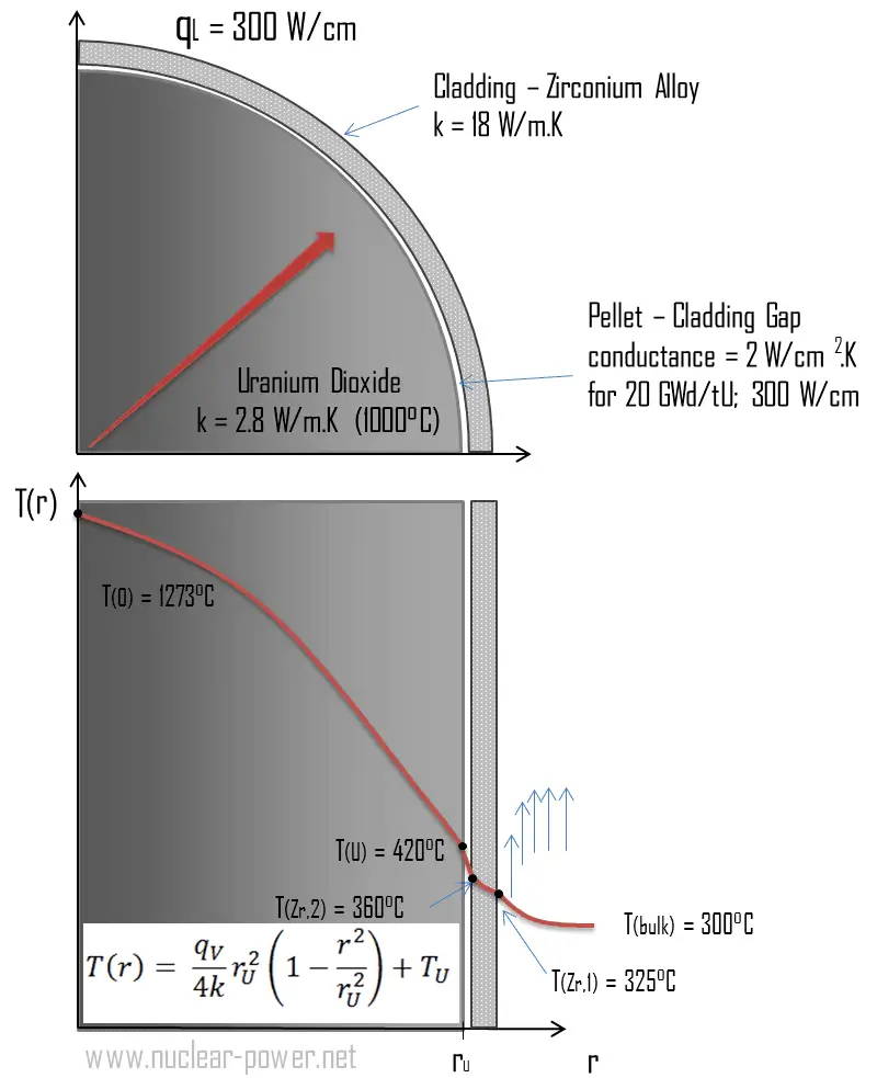
Consider the fuel cladding of inner radius rZr,2 = 0.408 cm and outer radius rZr,1 = 0.465 cm. Compared to fuel pellet, there is almost no heat generation in the fuel cladding (cladding is slightly heated by radiation). All heat generated in the fuel must be transferred via conduction through the cladding; therefore, the inner surface is hotter than the outer surface.
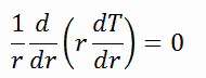
We must solve the heat conduction equation to find the temperature distribution through the cladding. Due to symmetry in the z-direction and azimuthal direction, we can separate variables and simplify this problem to a one-dimensional problem. Thus, we will only solve for the temperature as a function of radius, T(r). In this example, we will assume that there is strictly no heat generation within the cladding. For constant thermal conductivity, k, the appropriate form of the cylindrical heat equation, is:
The general solution of this equation is:

where C1 and C2 are the constants of integration.
1)
 Calculate the temperature distribution, T(r), in this fuel cladding, if:
- the temperature at the inner surface of the cladding is TZr,2 = 360°C
- the temperature of reactor coolant at this axial coordinate is Tbulk= 300°C
- the heat transfer coefficient (convection; turbulent flow) is h = 41 kW/m2.K.
- the averaged material’s conductivity is k = 18 W/m.K
- the linear heat rate of the fuel is qL = 300 W/cm, and thus the volumetric heat rate is qV = 597 x 106 W/m3
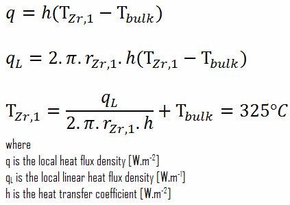
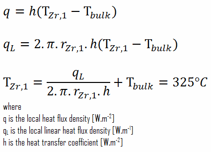
From the basic relationship for heat transfer by convection, we can calculate the outer surface of the cladding as:
As can be seen, in this case, we have given surface temperatures TZr,1 and TZr,2. This corresponds to the Dirichlet boundary condition. The constants may be evaluated using substitution into the general solution and are of the form:

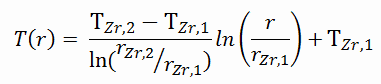
Solving for C1 and C2 and substituting them into the general solution, we then obtain:
∆T – cladding surface – coolant
Detailed knowledge of geometry, the outer radius of cladding, linear heat rate, convective heat transfer coefficient, and the coolant temperature determines ∆T between the coolant (Tbulk) and the cladding surface (TZr,1). Therefore we can calculate the cladding surface temperature (TZr,1) simply using Newton’s Law:
∆T in fuel cladding
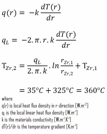
Detailed knowledge of geometry, outer and inner radius of cladding, linear heat rate, and the cladding surface temperature (TZr,1) determine ∆T between outer and inner surfaces of cladding. Therefore we can calculate the inner cladding surface temperature (TZr,2) simply using Fourier’s Law:
Fuel – Cladding Gap
There is also one very important phenomenon that influences the fuel temperature. As the fuel burnup increases, the fuel-cladding gap reduces. This reduction is caused by the swelling of the fuel pellets and cladding creep. Fuel pellet swelling occurs because fission gases cause the pellet to swell, resulting in a larger pellet volume. At the same time, the cladding is distorted by outside pressure (known as the cladding creep). These two effects result in direct fuel-cladding contact (e.g., at burnup of 25 GWd/tU). The direct fuel-cladding contact causes a significant reduction in fuel temperature profile because the overall thermal conductivity increases due to conductive heat transfer.
Loss of Tightness of Fuel Cladding – Fuel Reliability
Cladding prevents radioactive fission products from escaping the fuel matrix into the reactor coolant and contaminating it. The emergence of a leak in that cladding results in:
- the transport of specific chemical elements (fission products) that are stable and radioactive (iodine, xenon, krypton…) into the reactor’s primary circuit
- deposits of long-lived isotopes (cesium, strontium, technetium…), or even, in exceptional circumstances, of alpha emitters onto the piping of the primary circuit or ancillary circuits
- an increase in the overall level of irradiation for that circuit from the level already due to activation products (corrosion products, e.g., cobalt, chromium, iron in particular)
A leak thus poses a major challenge in operational terms for a power plant operator since it directly affects the radiological exposure workers are subjected to when running the plant or carrying out maintenance. Although fuel failures have rarely been a safety-related issue, their impact on plant operational costs due to:
- premature fuel discharge,
- following cycle shortening,
- possible unscheduled outages,
- increased spent fuel volume
One of the necessary steps to reach the zero defect goal is to understand the root causes of the failures and their mechanisms so that some corrective actions can be implemented, either through improvements in fuel design and fabrication by fuel suppliers or operational changes, such as reduced power maneuvering.
Special Reference: CEA, Nuclear Energy Division. Nuclear Fuels, ISBN 978-2-281-11345-7
Fuel Failure Mechanisms
Various fuel failure root causes have been identified in the past, and these causes were predominantly fabrication defects or fretting in the early days of PWR and BWR operations. The following list is not complete, and there are also failure mechanisms that are typical for certain reactor and fuel designs. It must also be noted that many fuel failure causes were never identified and remain unknown.
- Fretting. Fretting was one of the main failure mechanisms in the early dates of PWR and BWR operations, and it typically has two variants.
- Debris fretting. Debris fretting can be caused by any debris (foreign material – usually metallic) that can enter the fuel bundle and potentially become lodged between the spacer grid and a fuel rod. Fretting wear of fuel cladding can result in cladding penetration.
- Grid-to-rod fretting. Grid-to-rod fretting arises from the vibration of the fuel element generated by the high coolant
velocity through the spacing grid. Spacing grids are welded onto the guide tubes and ensured using springs and dimples, fuel rod support, and spacing. High coolant velocity can cause the rod to rub against the part of the spacer grid
that holds it. This type of cladding wear can be minimized by properly designing the spacing grid. Baffle-jetting is usually grouped under grid-to-rod fretting.
- Pellet-cladding interaction (PCI). Failures due to PCI are typical for power changes, rod movement, and plant startup. They usually occur within a few hours or days following a power ramp or control rod movement. This results, especially in startup ramp rate restrictions.
- Dryout. In BWRs, when the heat flux exceeds a critical value (CHF – critical heat flux), the flow pattern may reach the dry-out conditions (a thin film of liquid disappears). The heat transfer from the fuel surface into the coolant deteriorates, resulting in a drastically increased fuel surface temperature. This phenomenon can cause the failure of an affected fuel rod.
- Fabrication defects
- End-plug weld defects.
- Cladding creeps collapse. Cladding collapse can be caused by densifying the fuel pellets forming axial gaps in the pellet column, resulting in collapse from outer pressure. Since creep is time-dependent, full collapse typically occurs at higher burnup. This type of failure can be eliminated using pellets with moderate densification and pre-pressurization of rods.
- Missing pellet surface
- Internal Hydriding. Inadvertent inclusion of hydrogen-containing materials inside a fuel rod can result in hydriding and thus embrittlement fuel cladding. Hydrogen sources were mainly residual moisture or organic contamination in fuel pellets/rods. This cause of failure has been practically eliminated through improved manufacturing.
- Crud-induced corrosion. Crud-induced corrosion failures are either due to abnormally high heat flux exceeding heat flux or burnup corrosion limits or to water chemistry problems leading to excessive crud deposits. In BWRs, crud-induced corrosion was one of the major causes of fuel failure in the 1980s.
- Delayed hydride cracking (DHC). Delayed hydride cracking is time-dependent crack initiation and propagation through fracture of hydrides that can form ahead of the crack tip. This type of failure can be initiated by long cracks at the outer surface of the cladding, which can propagate in an axial/radial direction. This failure mechanism may potentially limit high burnup
operation. - Fuel handling damages
See also: IAEA, Review of fuel failures in water-cooled reactors. No. NF-T-2.1. ISBN 978–92–0–102610–1, Vienna, 2010.
See also: Stress-corrosion Cracking
See also: Hydrogen Embrittlement
Oxidation of Zirconium Alloys
The oxidation of zirconium alloys is one of the most studied processes in the entire nuclear industry. While many of these reports are written to address the reaction of fuel and steam with zirconium alloys in the case of a nuclear accident, there are still a substantial number of reports dealing with the oxidation of zirconium alloys at moderate temperatures of about 800 K and below.
The aggressive agent in this respect is primary circuit water, at a temperature of some 300° C. This oxidizes zirconium according to the reaction:
Zr + 2H2O→ZrO2 + 2H2
resulting in the formation of solid oxide on the metal’s surface. In summary, in the absence of neutron irradiation, the overall oxidation of zirconium and its alloys is fairly well understood. The oxidation rate depends upon the pressure of the oxygen or water vapor and scales approximately with pressure to the 1/6th power. The dependence of oxidation rate R on temperature and pressure can be expressed as:
R = 13.9·P1/6·exp(−1.47/kBT)
The oxidation rate R is here expressed in gram/(cm2·second); P is the pressure in the atmosphere, that is, the factor P1/6 = 1 at ambient pressure; the activation energy is 1.47 eV; kB is the Boltzmann constant (8.617×10⁻⁵ eV/K), and T is the absolute temperature in kelvins.
The enhancement in the oxidation rate in the presence of fast neutrons depends upon neutron intensity, temperature, water chemistry, dissolved oxygen in the water, and oxide layer thickness. Part of the hydrogen thus generated is incorporated into the metallic matrix, migrating under the effect of the thermal gradient to accumulate in the less hot regions, forming hydrides that are liable to cause brittleness in the cladding as the fuel cools down. The two processes, oxidation, and hydridation, are thus intimately bound together.
To date, the most commonly used alloy in PWRs has been Zircaloy 4. However, currently, this is being replaced by new zirconium–niobium-based alloys, exhibiting better corrosion resistance. The maximum temperature at which zirconium alloys can be used in water-cooled reactors depends on their corrosion resistance. Alloys of type Zircalloy, in which tin is the basic alloying element that improves their mechanical properties, have a wide distribution worldwide. However, in this case, the corrosion resistance in water and steam is decreased, resulting in the need for additional alloying. The improvement brought about by the additive niobium probably involves a different mechanism. The high corrosion resistance of niobium alloyed metals in water and steam at temperatures of 400–550°C is caused by their ability to passivation with the formation of protective films.
Fuel Cladding Integrity – Postulated Accidents
- LOCA conditions. LOCA (loss of coolant accident) accidents are postulated accidents that result in a loss of reactor coolant at a rate over the capability of the reactor makeup system from breaks in the reactor coolant pressure boundary, up to and including a break equivalent in size to the double-ended rupture of the largest pipe of the reactor coolant system. LOCA conditions are associated with a rapid decrease in system pressure, cladding ballooning, rupture, and high-temperature steam oxidation. In January 1974, the USNRC published 10 CFR 50.46 establishing acceptance criteria for the ECCSs for LWRs, addressing safety limits that must be assured under LOCA conditions:
- The maximum zircaloy cladding temperature (Peak Cladding Temperature),
- The maximum oxidation of cladding,
- The maximum amount of hydrogen generated by the chemical reaction of the zirconium alloy with water and/or steam,
- Coolable core geometry,
- Long-term cooling.
- Non-LOCA conditions. Non-LOCA conditions affecting fuel cladding integrity typically include a main steamline break (MSLB) and reactivity-initiated accidents (RIAs). MSLBs are associated with power excursion and the risk of departure from nucleate boiling, resulting in high-temperature steam oxidation. RIAs consist of postulated accidents involving a sudden and rapid positive reactivity insertion. In these accidents, the large and rapid deposition of energy in the fuel can result in melting, fragmentation, and dispersal of fuel. The mechanical action associated with fuel dispersal can be sufficient to destroy the fuel’s cladding and rod-bundle geometry and produce pressure pulses in the primary system.
See also: Enthalpy of Nuclear Fuel
Departure from Nucleate Boiling
In pressurized water reactors, one of the key safety requirements is that a departure from nucleate boiling (DNB) will not occur during steady state operation, normal operational transients, and anticipated operational occurrences (AOOs). Fuel cladding integrity will be maintained if the minimum DNBR remains above the 95/95 DNBR limit for PWRs ( a 95% probability at a 95% confidence level). DNB criterion is one of the acceptance criteria in safety analyses and constitutes one of the safety limits in technical specifications.
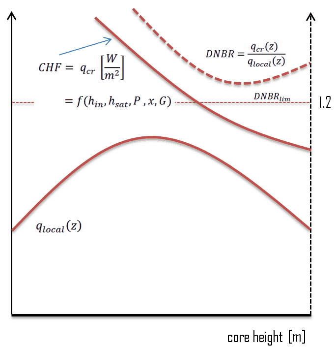 This phenomenon occurs in the subcooled or low-quality region. The behavior of the boiling crisis depends on many flow conditions (pressure, temperature, flow rate). Still, the boiling crisis occurs at relatively high heat fluxes and appears to be associated with the cloud of bubbles adjacent to the surface. These bubbles or film of vapor reduces the amount of incoming water. Since this phenomenon deteriorates the heat transfer coefficient and the heat flux remains, heat then accumulates in the fuel rod, causing a dramatic rise of cladding and fuel temperature. A very high-temperature difference is required to transfer the critical heat flux produced from the fuel rod’s surface to the reactor coolant (through the vapor layer). This temperature rise causes unacceptable oxidation of the fuel cladding.
An important duty of the plant operator is to control plant parameters such that a safe margin to DNB (or distance from DNB on the heat transfer curve) is maintained. Any sudden, large change in the following plant parameters/directions will decrease the margin to DNB:
- Decrease in reactor coolant pressure
- Decrease in reactor coolant flow rate
- Increase in reactor power
- Increase in reactor coolant inlet temperature
Therefore, the function of the operators and the plant design is to prevent a sudden, large change in these plant parameters.
High-Temperature Steam Oxidation of Zirconium Alloys
As was written in the previous section, the oxidation of zirconium alloys is one of the most studied processes in the nuclear industry. While many of these reports are written to address the reaction of fuel and steam with zirconium alloys in the case of a nuclear accident, there are still a substantial number of reports dealing with the oxidation of zirconium alloys at moderate temperatures of about 800 K and below. The aggressive agent in this respect is primary circuit water, at a temperature of some 300° C. This oxidizes zirconium according to the reaction:
Zr + 2H2O→ZrO2 + 2H2
resulting in the formation of solid oxide on the metal’s surface. The reaction is always exothermic, and the heat of the reaction is similar for all types of zirconium-based alloys. The rate of reaction increases smoothly, although strongly, with temperature.
At high temperatures, the exothermic reaction of Zr-base alloys with steam is much more intensive and hazardous for the safety of nuclear power plants during accidents like a loss-of-coolant accident (LOCA). The main problem of high-temperature oxidation is that zirconium cladding rapidly reacts with water steam at high temperatures. The oxidation kinetics of relevant zirconium alloys appears to be parabolic in the temperature range of 1000-1500°C for many Zr-based alloys. Above 1577°C, the oxide layer transforms from tetragonal to cubic, and the oxidation rate even increases. Moreover, oxidation of zirconium by water is accompanied by a release of hydrogen gas. This oxidation is accelerated at high temperatures, e.g., inside a reactor core, if the fuel assemblies are no longer completely covered by liquid water and insufficiently cooled. Metallic zirconium is then oxidized by water/steam to form hydrogen gas according to the following redox reaction:
Zr + 2H2O→ZrO2 + 2H2 (Q = 190 kJ/mol; Baker and Just)
Zirconium cladding in the presence of D2O deuterium oxide is frequently used as the moderator and coolant in next-gen pressurized heavy water reactors that CANDU-designed nuclear reactors use would express the same oxidation on exposure to deuterium oxide steam as follows:
Zr + 2D2O→ZrO2 + 2D2
Although only occurring at high temperatures, this exothermic reaction is similar to that of alkali metals (such as sodium or potassium) with water.
Above approximately 800°C, there is a phase transformation from the hexagonal (HCP) α-phase to the cubic β-phase (BCC). Oxygen, which diffuses into the remaining metal, stabilizes the α-phase. With cooling, the β phase will transform back to the α phase in which the oxygen concentration is significantly different from that of the oxygen-stabilized α and “prior β.” The problem is that these phase transitions make this material very brittle. Therefore, there are also three current LOCA licensing criteria (according to 10 CFR 50.46 – ECCS Acceptance Criteria for LWR) for preventing fuel failure (it can fail upon rewet during the introduction of emergency core cooling in a reactor accident or fail by overstraining under oxide cracks) due to oxygen and hydrogen embrittlement and these criteria limit:
- Maximum Cladding Oxidation. The calculated total oxidation of the cladding shall nowhere exceed 0.17 times the total cladding thickness before oxidation. In other words, this criterion limits maximum Equivalent Cladding Reacted (ECR) to 17% during high-temperature steam oxidation to ensure adequate ductility during the Emergency Core Cooling System (ECCS) quench and possible post-LOCA seismic events. After the 1973 ECCS hearing, the Commission’s opinion was that retention of ductility in the Zircaloy cladding was the best guarantee of its remaining intact during a loss-of-coolant accident. The original 17% maximum cladding oxidation limit was derived from ring compression tests performed on oxidized rings of Zircaloy cladding that were intended to show under what temperature and oxidation conditions residual ductility would be present after a LOCA. During a loss-of-coolant accident (LOCA), fuel rods are expected to balloon, rupture, and then oxidize as the temperature rises toward the peak cladding temperature. Oxidation inside the cladding is also expected in the ruptured region, and maximum cladding oxidation is always found in that location. Regulation §50.46 requires the calculation of double-sided oxidation in the ruptured region, which is this amount of oxidation, and it is compared with the 17% limit to demonstrate ductility.
- Peak Cladding Temperature. The calculated maximum fuel element cladding temperature shall not exceed 2200°F (1204°C). This criterion ensures the validity of the ECR criterion.
- Parabolic oxidation kinetics. The oxidation kinetics of relevant zirconium alloys appears to be parabolic in the temperature range of 1000-1500°C for many Zr-based alloys. During the period when high cladding temperatures occur, the heat sources are decay heat and oxidation heat. As temperature increases, the oxidation heat becomes dominant such that the entire heat source increases rapidly with temperature. At approximately 2200°F, the oxidation heat (generated from typical zirconium alloys) equals the decay heat generated after 8 hours from reactor shutdown.
- Phase transition and additional embrittlement. As was written, Above approximately 800°C, there is a phase transformation from the hexagonal (HCP) α-phase to the cubic β-phase (BCC). Oxygen, which diffuses into the remaining metal, stabilizes the α-phase. The problem is that above 2200°F, these phase transitions and oxygen concentration make this material very brittle. Above 1577°C, the oxide layer transforms from tetragonal to cubic, and the oxidation rate even increases, but this is well above the range of interest for a limit. Below 1000°C, the weight gain deviates from parabolic behavior as the alloys transform from the β-phase to the mixed β+α-phase to the α-phase. Phase transformation temperatures depend on alloy type, oxygen, and hydrogen concentrations. Therefore, peak cladding temperature was discussed extensively in the 1973 ECCS hearing, and the 2200°F value arose in connection with the 17% maximum cladding oxidation value. The 2200°F value was chosen because the relation between maximum cladding oxidation and ductility broke down for temperatures between 2200 and 2400°F (no data in between). It would, of course, have been possible to choose a higher peak cladding temperature and a correspondingly lower maximum cladding oxidation value.
- Maximum hydrogen generation. The calculated total amount of hydrogen generated from the chemical reaction of the cladding with water or steam shall not exceed 0.01 times the hypothetical amount that would be generated if all of the metal in the cladding cylinders surrounded the fuel, excluding the cladding surrounding the plenum volume, were to react.
Note that loss-of-coolant accidents (LOCA’s) are hypothetical accidents that would result from the loss of reactor coolant, at a rate over the capability of the reactor coolant makeup system, from breaks in pipes in the reactor coolant pressure boundary up to and including a break equivalent in size to the double-ended rupture of the largest pipe in the reactor coolant system.
Special Reference: Baker, L., Just, L.C., Studies of Metal Water Reactions at High Temperatures, III. Experimental and Theoretical Studies of the Zirconium-Water Reaction, ANL-6548, page 7, May 1962
Special Reference: M.C. Billone, H.M. Chung, and Y. Yan. STEAM OXIDATION KINETICS OF ZIRCONIUM ALLOYS. Argonne National Laboratory, June 4, 2002.
Special Reference: F.C. Iglesias, B.J. Lewis, C. Desgranges, C. Toffolon. Clad-coolant chemical interaction. NEA/NSC/R-2015-5. NEA, OECD, 2015.
Baker-Just Correlation
In 1973, the Baker-Just correlation was selected as the best correlation available and was included as a requirement in Appendix K of 10 CFR 50.46 for calculating the heating rate due to oxidation, hydrogen generation, and the Effective Cladding Reacted (ECR) because it was available in 1973. The Baker-Just equation and more recent correlations can be represented as an Arrhenius relation (e-Q/RT) with an activation energy Q and an exponential dependence on temperature T (R is the universal gas constant). Thus, the oxidation rate and, hence, the heat generation rate increase rapidly as temperature increases. The integrated form of the Baker-Just correlation (BJ) for weight/surface-area (w) of zirconium consumed during steam oxidation is
w2 = 33.3×10⁶ t exp(-45500/RT), (mg/cm2)2
where t is time in seconds, T is the temperature in K, and R = 1.987. This equation applies to isothermal oxidation in steam for fresh cladding with no protective, pre-transient oxide layer. However, this correlation has the least significant database and justification of all those reviewed. Oxidation kinetics studies on various zirconium alloys conducted since 1962 – particularly in the 1970s – have demonstrated that the Baker-Just correlation over-predicts weight gain and zirconium consumed by as much as 30% at the peak cladding temperature (1204°C) allowed by 10CFR50.46. USNRC Regulatory Guide 1.157 (May 1989) allows the use of a best-estimate correlation (e.g., Cathcart-Pawel) for temperatures greater than 1078°C.
Special Reference: Baker, L., Just, L.C., Studies of Metal Water Reactions at High Temperatures, III. Experimental and Theoretical Studies of the Zirconium-Water Reaction, ANL-6548, page 7, May 1962
Special Reference: M.C. Billone, H.M. Chung, and Y. Yan. STEAM OXIDATION KINETICS OF ZIRCONIUM ALLOYS. Argonne National Laboratory, June 4, 2002.
Special Reference: F.C. Iglesias, B.J. Lewis, C. Desgranges, C. Toffolon. Clad-coolant chemical interaction. NEA/NSC/R-2015-5. NEA, OECD, 2015.
Advanced Fuel Clad
While current nuclear fuel designs have operated very well under normal plant conditions, existing nuclear fuel designs can be challenged when put under beyond-design-basis severe-accident scenarios. In such conditions, the long-term loss of coolant and the resulting high temperatures of the fuel can lead to the degradation of the fuel cladding and the early release of fission products.
Proposed ATF concepts seek to reduce severe accident (SA) risks by increasing the coping time available to operators for accident response, reducing the extent and rate of heat and hydrogen production from high-temperature (HT) steam oxidation, or reducing severe accident consequences by enhancing fission product (FP) retention. The desired attributes for a practical ATF cladding material are quite rigorous. In addition to good material properties at high temperatures, the candidate material must be compatible with current fuel/core designs and provide economic operation, including good neutronics. Moreover, from an operational perspective, it must be highly reliable, have corrosion resistance, and exhibit low embrittlement at high burnups.
According to the NEA report, five different classes of cladding designs were the object of the review:
- Coated and improved Zr-alloys,
- Advanced steels,
- Refractory metals,
- SiC and SiC/SiC-composite claddings
- non-fuel components such as SiC/SiC channel boxes or accident-tolerant control rods (ATCR).