In PWRs, the reactor core consists of assemblies of fuel rods featuring a zirconium alloy cladding, holding uranium oxide pellets (with uranium enriched to ~ 4% U-235) or MOX pellets (mixed uranium-plutonium oxides [(U, Pu)O2], with a Pu content of 5–10%). Fuel fabrication is the final step of the front end of the nuclear fuel cycle. In this step, a complete fuel assembly is fabricated. Since a fuel assembly consists of several structural parts, this step may be processed at different locations, and these parts may also be prefabricated. Typical PWR fuel assembly consists of:
- Fuel Pellets. Most PWRs use uranium fuel, which is in the form of uranium dioxide. Uranium dioxide is a black semiconducting solid with very low thermal conductivity. On the other hand, uranium dioxide has a very high melting point and has well-known behavior. The UO2 is pressed into pellets, which are then sintered into the solid cylinder (with a height and diameter of about 1 centimeter, the height being greater than the diameter). The dimensions of the fuel pellets and other components of the fuel assembly are precisely controlled to ensure consistency in the characteristics of the fuel. These pellets are then loaded and encapsulated within a fuel rod (a metallic cladding tube), made of zirconium alloys due to its very low absorption cross-section (unlike stainless steel). The surface of the tube, which covers the pellets, is called fuel cladding. Fuel rods are the base element of a fuel assembly. Fuel rods have the purpose of containing fission products, ensuring mechanical support for the pellets, and allowing the heat removal to the coolant fluid of the heat generated by nuclear reactions. A typical fuel rod has a length of some 4 m, with a diameter of around 1 cm.
- Fuel Cladding. Zirconium is a lustrous, grey-white, strong transition metal that resembles hafnium and titanium to a lesser extent. Zirconium is mainly used as a refractory and opacifier, although small amounts are used as an alloying agent for its strong resistance to corrosion. Zirconium alloy (e.g., Zr + 1%Nb) is widely used as a cladding for nuclear reactor fuels. The desired properties of these alloys are a low neutron-capture cross-section and resistance to corrosion under normal service conditions. Zirconium alloys have lower thermal conductivity (about 18 W/m.K) than pure zirconium metal (about 22 W/m.K).
- Fuel Rods. Aside from the stacked pellets and cladding tube, the rod comprises two welded end plugs, a plenum (or expansion chamber) to accommodate the fission gases released, and a spring inside the plenum, holding the fuel column in position. The fuel rod is filled with helium at a pressure of about 25 bars to compensate, in part, for the outside pressure, in the primary circuit (155 bars in PWRs).
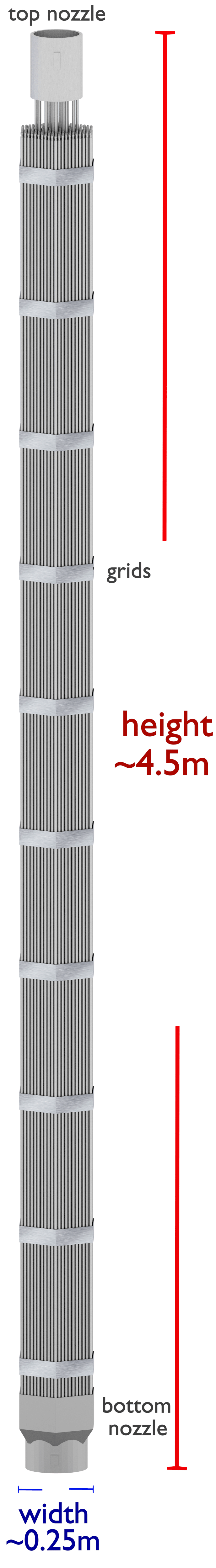
- Top Nozzle. A PWR fuel assembly comprises a bottom nozzle into which rods are fixed through the lattice, and it is ended by a top nozzle to finish the whole assembly. There are spacing grids between these nozzles, and these grids ensure an exact guiding of the fuel rods. The bottom and top nozzles are heavily constructed as they provide much mechanical support for the fuel assembly structure, and the top nozzle ensures the assembly handling function.
- Bottom Nozzle. Provides the mechanical support for the fuel assembly structure. The bottom nozzle features a debris mitigation device to catch traveling foreign bodies, which had formed, at one time, the chief cause of cladding failure.
- Spacing Grid. Ensures an exact guiding of the fuel rods. Spacing grids are welded onto the guide tubes and ensured, using springs and dimples, fuel rod support, and spacing. They may carry vanes, allowing improved mixing of fluid streams, thus enhancing the assembly’s thermal-hydraulic performance.
- Guide thimble Tubes. A vacant tube for control rods or incore instrumentation. The absorber rods in the control clusters slide within the guide tubes.
- Instrumentation Tube. An instrumentation tube is a vacant tube only for incore instrumentation, such as the incore neutron flux monitoring system.
The fuel assembly constitutes the base element of the nuclear reactor core. The reactor core (PWR type) contains about 157 fuel assemblies (depending on the reactor type). Western PWRs use a square lattice arrangement, and assemblies are characterized by the number of rods they contain, typically 17×17 in current designs. The enrichment of fuel rods is never uniform, and the enrichment is differentiated in the radial and axial directions. This arrangement improves power distribution and improves fuel economy.
Russian VVER-type reactors use a fuel characterized by their hexagonal arrangement but is otherwise of similar length and structure to other PWR fuel assemblies.
A PWR fuel assemblies stand between four and five meters high, is about 20 cm across, and weighs about 800 kg (of which about 500kg is uranium). The assemblies have vacant rod positions for control rods or in-core instrumentation. Control rods, in-core instrumentation, neutron source, or a test segment can be vertically inserted into a vacant tube called the guide thimble.
Special Reference: CEA, Nuclear Energy Division. Nuclear Fuels, ISBN 978-2-281-11345-7
]