Source: wikipedia.org CC BY-SA
We have discussed convective heat transfer in the preceding chapters with a very important assumption, and we have assumed a single-phase convective heat transfer without any phase change. This chapter focuses on convective heat transfer associated with the change in phase of a fluid. In particular, we consider processes that can occur at a solid-liquid or solid–vapor interface, namely, boiling (liquid-to-vapor phase change) and condensation (vapor-to-liquid phase change).
Latent heat effects associated with the phase change are significant for these cases. Latent heat, also known as the enthalpy of vaporization, is the amount of heat added to or removed from a substance to produce a change in phase. This energy breaks down the intermolecular attractive forces and must provide the energy necessary to expand the gas (the pΔV work). When latent heat is added, no temperature change occurs.
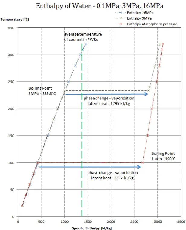
The enthalpy of vaporization is a function of the pressure at which that transformation takes place.
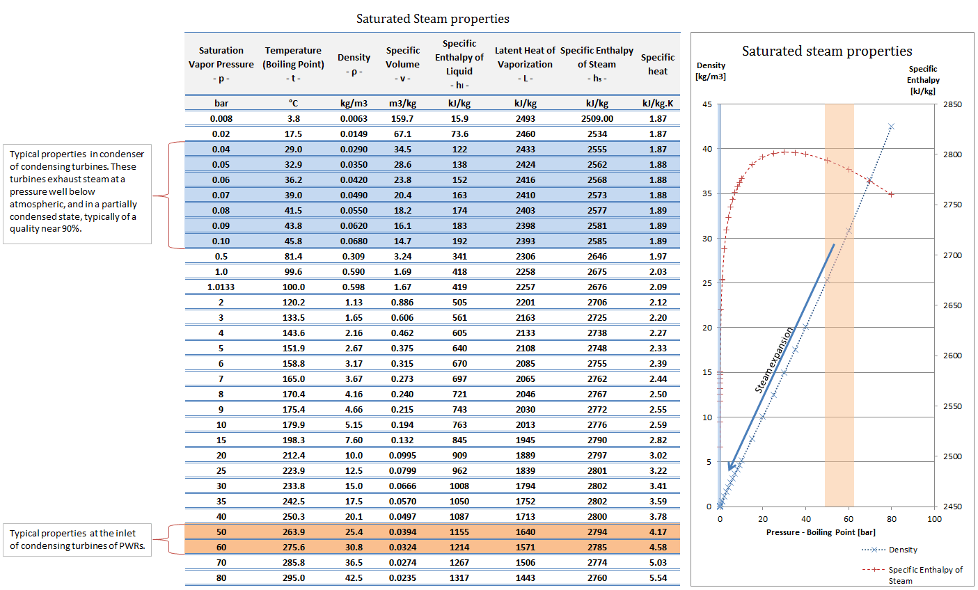
Latent heat of vaporization – water at 0.1 MPa (atmospheric pressure)
hlg = 2257 kJ/kg
Latent heat of vaporization – water at 3 MPa (pressure inside a steam generator)
hlg = 1795 kJ/kg
Latent heat of vaporization – water at 16 MPa (pressure inside a pressurizer)
hlg = 931 kJ/kg
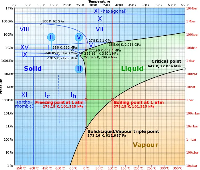
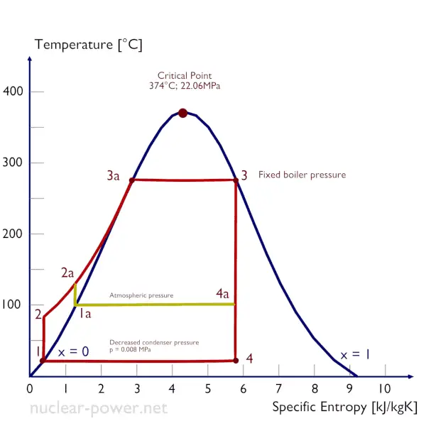
 The heat of vaporization diminishes with increasing pressure while the boiling point increases, and it vanishes completely at a certain point called the critical point. Above the critical point, the liquid and vapor phases are indistinguishable, and the substance is called a supercritical fluid.
The change from the liquid to the vapor state due to boiling is sustained by heat transfer from the solid surface; conversely, condensation of a vapor to the liquid state results in heat transfer to the solid surface. Boiling and condensation differ from other forms of convection in that they depend on the latent heat of vaporization, which is very high for common pressures. Therefore large amounts of heat can be transferred during boiling and condensation essentially at a constant temperature. Heat transfer coefficients, h, associated with boiling and condensation are typically much higher than those encountered in other forms of convection processes that involve a single phase.
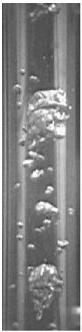
This is due to the fact even in a turbulent flow. There is a stagnant fluid film layer (laminar sublayer) that isolates the surface of the heat exchanger. This stagnant fluid film layer plays a crucial role in the convective heat transfer coefficient. It is observed that the fluid comes to a complete stop at the surface and assumes a zero velocity relative to the surface. This phenomenon is known as the no-slip condition, and therefore, at the surface, energy flow occurs purely by conduction. But in the next layers, both conduction and diffusion-mass movement occur at the molecular or macroscopic levels. Due to the mass movement, the rate of energy transfer is higher. As was written, nucleate boiling at the surface effectively disrupts this stagnant layer. Therefore, nucleate boiling significantly increases the ability of a surface to transfer thermal energy to the bulk fluid.
 By definition, multiphase flow is the interactive flow of two or more distinct phases with common interfaces in, say, a conduit. Each phase, representing a volume fraction (or mass fraction) of solid, liquid, or gaseous matter, has its own properties, velocity, and temperature.
A multiphase flow can be a simultaneous flow of:
- Materials with different states or phases (e.g., water-steam mixture).
- Materials with different chemical properties but in the same state or phase (e.g., oil droplets in water).
There are many combinations in industrial processes, but the most common being the simultaneous flow of steam and liquid water (as encountered in steam generators and condensers). In reactor engineering, a great deal of study has been performed on the nature of two-phase flow in case of a loss-of-coolant accident (LOCA), an accident of importance in reactor safety, and all thermal-hydraulic analyses (DNBR analyses).
Characteristics of Two-phase Fluid Flow
All two-phase flow problems have characteristically different features from those found in single-phase problems.
- In the case of steam and liquid water, the density of the two phases differs by a factor of about 1000. Therefore the influence of gravitational body force on multiphase flows is of much greater importance than in the case of single-phase flows.
- The sound speed changes dramatically for materials undergoing a phase change and can be orders of magnitude different. This significantly influences a flow through an orifice.
- The relative concentration of different phases is usually a dependent parameter of great importance in multiphase flows, while it is a parameter of no consequence in single-phase flows.
- The phase change means flow-induced pressure drops can cause further phase change (e.g., water can evaporate through an orifice), increasing the relative volume of the gaseous, compressible medium and increasing efflux velocities, unlike single-phase incompressible flow where decreasing of an orifice would decrease efflux velocities.
- The spatial distribution of the various phases in the flow channel strongly affects the flow behavior.
- There are many types of instabilities in multiphase flow.
Boiling Point – Saturation
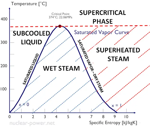
In thermodynamics, the term saturation defines a condition in which a mixture of vapor and liquid can exist together at a given temperature and pressure. The temperature at which vaporization (boiling) occurs for a given pressure is called the saturation temperature or boiling point. The pressure at which vaporization (boiling) occurs for a given temperature is called the saturation pressure.
When the vapor quality is equal to 0, it is referred to as the saturated liquid state (single-phase). On the other hand, when the vapor quality is equal to 1, it is referred to as the saturated vapor state or dry steam (single-phase). We talk about a vapor-liquid mixture or wet steam (two-phase mixture) between these two states. At constant pressure, the addition of energy does not change the mixture’s temperature, but the vapor quality and specific volume change.
Saturation in Pressurizer
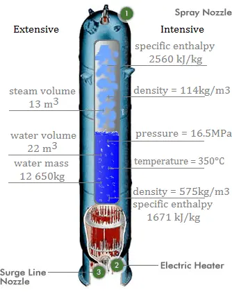
A pressurizer is a component of a pressurized water reactor. Pressure in the primary circuit of PWRs is maintained by a pressurizer, a separate vessel connected to the primary circuit (hot leg), and partially filled with water heated to the saturation temperature (boiling point) for the desired pressure by submerged electrical heaters. The temperature in the pressurizer can be maintained at 350 °C (662 °F), which gives a subcooling margin (the difference between the pressurizer temperature and the highest temperature in the reactor core) of 30 °C. Subcooling margin is a very important safety parameter of PWRs since the boiling in the reactor core must be excluded. The basic design of the pressurized water reactor includes such a requirement that the coolant (water) in the reactor coolant system must not boil. To achieve this, the coolant in the reactor coolant system is maintained at a pressure sufficiently high that boiling does not occur at the coolant temperatures experienced while the plant is operating or in an analyzed transient.
Functions
Pressure in the pressurizer is controlled by varying the temperature of the coolant in the pressurizer. For these purposes, two systems are installed. Water spray system and electrical heaters system. The volume of the pressurizer (tens of cubic meters) is filled with water on saturation parameters and steam. The water spray system (relatively cool water – from the cold leg) can decrease the pressure in the vessel by condensing the steam on water droplets sprayed in the vessel. On the other hand, the submerged electrical heaters are designed to increase the pressure by evaporating the water in the vessel. Water pressure in a closed system tracks water temperature directly; as the temperature goes up, the pressure goes up.
Boiling in Steam Generator
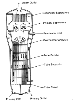
Steam generators are heat exchangers that convert feedwater into steam from heat produced in a nuclear reactor core, and the steam produced drives the turbine. They are used in most nuclear power plants, but there are many types according to the reactor type.
The hot primary coolant (water 330°C; 626°F; 16MPa) is pumped into the steam generator through the primary inlet. High pressure of primary coolant is used to keep the water in the liquid state, and boiling of the primary coolant shall not occur. The liquid water flows through hundreds or thousands of tubes (usually 1.9 cm in diameter) inside the steam generator. The feedwater (secondary circuit) is heated from ~260°C 500°F to the boiling point of that fluid (280°C; 536°F; 6,5MPa). Heat is transferred through the walls of these tubes to the lower pressure secondary coolant located on the secondary side of the exchanger where the coolant evaporates to pressurized steam (saturated steam 280°C; 536°F; 6,5 MPa). The pressurized steam leaves the steam generator through a steam outlet and continues to the steam turbine. Heat transfer is accomplished without mixing the two fluids to prevent the secondary coolant from becoming radioactive. The primary coolant leaves (water 295°C; 563°F; 16MPa) the steam generator through the primary outlet and continues through a cold leg to a reactor coolant pump and then into the reactor.
Condensation in Main Condenser
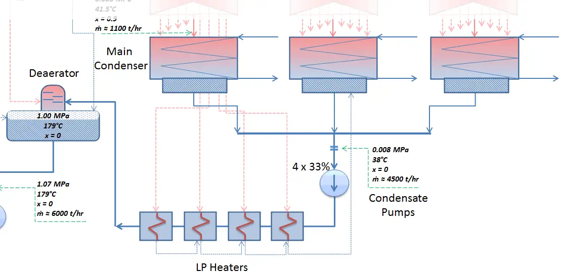 The condenser must maintain a sufficient low vacuum to increase the power plant efficiency. The vacuum pumps maintain a sufficient vacuum in the condenser by extracting air and uncondensed gases. The lowest feasible condenser pressure is the saturation pressure corresponding to the ambient temperature (e.g., the absolute pressure of 0.008 MPa, which corresponds to 41.5°C). Note that there is always a temperature difference between (around ΔT = 14°C) the condenser temperature and the ambient temperature, which originates from condensers’ finite size and efficiency. Since neither the condenser is a 100% efficient heat exchanger, there is always a temperature difference between the saturation temperature (secondary side) and the temperature of the coolant in the cooling system. Moreover, there is design inefficiency, which decreases the turbine’s overall efficiency. Ideally, the steam exhausted into the condenser would have no subcooling. But real condensers are designed to subcool the liquid by a few degrees Celsius to avoid the suction cavitation in the condensate pumps. But, this subcooling increases the inefficiency of the cycle because more energy is needed to reheat the water.
The goal of maintaining the lowest practical turbine exhaust pressure is a primary reason for including the condenser in a thermal power plant. The condenser provides a vacuum that maximizes the energy extracted from the steam, resulting in a significant increase in network and thermal efficiency. But also this parameter (condenser pressure) has its engineering limits:
- Decreasing the turbine exhaust pressure decreases the vapor quality (or dryness fraction). At some point, the expansion must be ended to avoid damages that could be caused to blades of steam turbine by low-quality steam.
- Decreasing the turbine exhaust pressure significantly increases the specific volume of exhausted steam, which requires huge blades in the last rows of a low-pressure stage of the steam turbine.
In a typical wet steam turbine, the exhausted steam condenses in the condenser, and it is at a pressure well below atmospheric (absolute pressure of 0.008 MPa, which corresponds to 41.5°C). This steam is in a partially condensed state (point F), typically of a quality near 90%. Note that the pressure inside the condenser is also dependent on the ambient atmospheric conditions:
- air temperature, pressure, and humidity in case of cooling into the atmosphere
- water temperature and the flow rate in case of cooling into a river or sea
 An increase in the ambient temperature causes a proportional increase in pressure of exhausted steam (ΔT = 14°C is usually a constant); hence the thermal efficiency of the power conversion system decreases. In other words, the electrical output of a power plant may vary with ambient conditions, while the thermal power remains constant.
To maintain the parameters inside the condenser (0.008 MPa and 41.5 °C), the cooling water from the cooling system must be sufficiently cold, and there cannot be a large temperature difference between the outlet and inlet water temperature. Hence the flow rate through the cooling system must be very high. The flow rate through the cooling system (with wet cooling towers) may be up to 100 000 m3/h (27.7 m3/s). The condenser inlet water may have about 22°C (strongly depending on ambient conditions), while the condenser outlet may have about 25°C. The seawater cooling systems operate at higher flow rates, for example, 130 000 m3/h.