In previous chapters (nuclear chain reaction), it was derived that leakage of neutrons from the system significantly influences the criticality of a reactor. For thermal reactors, two variables are defined to describe the leakage process:
The fast non-leakage probability (Pf) and the thermal non-leakage probability (Pt) may be combined into one term that gives the fraction of all neutrons that do not leak out of the reactor core. This term is called the total non-leakage probability and is given the symbol PNL.
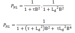
We can rewrite this equation without a substantial loss of accuracy for large reactors simply by replacing the diffusion length Ld and the fermi age τ with the migration length M in the one group equation. The term B4 is very small for large reactors, and therefore it can be neglected. We may then write.
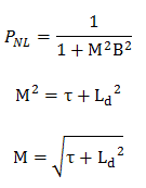
where M is the migration area (m2), the migration length is defined as the square root of the migration area. As can be seen, the total non-leakage probability of large reactors is primarily a function of the migration area.
In LWRs, the neutron reflector is installed for the following purposes:
- The neutron flux distribution is “flattened“, i.e., the ratio of the average flux to the maximum flux is increased. Therefore reflectors reduce the non-uniformity of the power distribution.
- Because of the higher flux at the edge of the core, there is much better utilization in the peripheral fuel assemblies. In the outer regions of the core, this fuel now contributes much more to the total power production.
- The neutron reflector scatters back (or reflects) into the core many neutrons that would otherwise escape. The neutrons reflected into the core are available for a chain reaction. This means that the minimum critical size of the reactor is reduced. Alternatively, if the core size is maintained, the reflector makes additional reactivity available for higher fuel burnup. The decrease in the critical size of the core required is known as reflector savings.
- Neutron reflectors reduce neutron leakage, i.e., to reduce the neutron fluence on a reactor pressure vessel.
- Neutron reflectors reduce a coolant flow bypass of a core.
- Neutron reflectors serve as a thermal and radiation shield of a reactor core.
The reflector’s efficiency is measured by the ratio of the number of neutrons reflected into the reactor to the number entering the reflector. This ratio is called the albedo or the reflection coefficient. The albedo can be expressed in terms of neutron currents as:
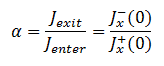
The value of the albedo will depend on the composition and thickness of the reflector. An infinite reflector will have the maximum albedo. Still, in all practical cases, the geometry of a reflector must conform to the geometry of a reactor core and a reactor pressure vessel. For sufficiently thick reflectors, it can be derived that albedo becomes:

where Drefl is the diffusion coefficient in the reflector, and the Lrefl is the reflection’s diffusion length.
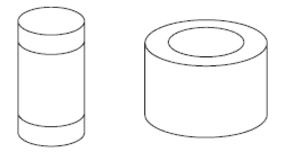 In general, neutron reflector may be axial and radial, but, for example, in pressurized water reactors the axial reflector does not form any special device. The neutrons are reflected by the core inlet and outlet coolant. On the other hand, common water volume cannot be used as a reflector in the radial direction because it is of the highest importance to maintain high flow rates in the core and not bypass fuel assemblies. Therefore the radial neutron reflectors are installed in PWR and BWR reactor cores. The design of such radial neutron reflectors may vary, but we can distinguish between two basic types:
Flux in a Reflected Thermal Reactor – One-group Method
The mathematical treatment of a reflected thermal reactor can be illustrated most simply by considering a slab reactor of thickness extending from x= -a/2 to x= +a/2 reflected on both sides by a non-multiplying slab (neutron reflector) of thickness b. Neutrons will be considered as monoenergetic with thermal energy. Although the one-group method may provide reasonable results for the reactor, this method does not accurately predict the flux.
For the determination of the flux distribution in the reactor and the reflector, the following diffusion equations in these zones need to be solved:
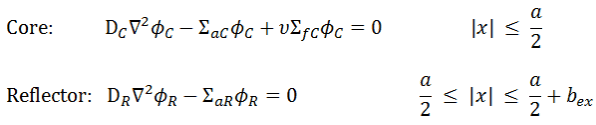
where a is the real width of the reactor and b is the outer dimension of the reflector (bex is the outer dimension, including the extrapolation distance). With problems involving two different diffusion media, the following boundary conditions must be satisfied:
1,2. Interface Conditions
At interfaces between two different diffusion media (such as between the reactor core and the neutron reflector), on physical grounds, the neutron flux and the normal component of the neutron current must be continuous. In other words, φ and J are not allowed to show a jump.
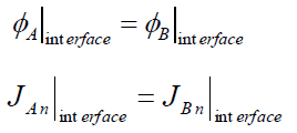
It must be added, as J must be continuous, the flux gradient will show a jump if the diffusion coefficients in both media differ from each other. Since the solution of these two diffusion equations requires four boundary conditions, we have to use two boundary conditions more.
3. Finite Flux Condition
The solution must be finite in those regions where the equation is valid, except perhaps at artificial singular points of a source distribution. This boundary condition can be written mathematically as:
![]()
4. Vacuum Boundary Condition
The vacuum boundary condition requires the relative neutron flux near the boundary to have a slope of -1/d, i.e., the flux would extrapolate linearly to 0 at a distance d beyond the boundary (d is the extrapolated length). This zero flux boundary condition is more straightforward, and it can be written mathematically as:
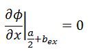
If d is not negligible, the physical dimensions of the reactor are increased by d, and this condition can be written as Φ(a/2 + bex) = 0.
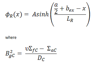
The solution in the core satisfying these boundary conditions is:

where
The solution in the reflector satisfying these boundary conditions is:

Flux in a Reflected Thermal Reactor – Two-group Method
 It was pointed out, the one-group method may provide reasonable results for the reactor, but this method does not accurately predict the flux. The energy of neutrons must be grouped into at least two groups to be more accurate. The two-group energy model leads to very interesting and important results that must be considered in the design of nuclear reactors.
In this method, the entire range of neutron energies is divided into 2 intervals (fast and thermal groups). All neutrons within each interval are lumped into a group, and in this group, all parameters such as the diffusion coefficients or cross-sections are averaged.
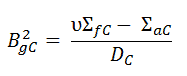
To find the solution in a reactor core and a reflector, it is necessary to solve the following diffusion equations for the fast and thermal energy groups are:
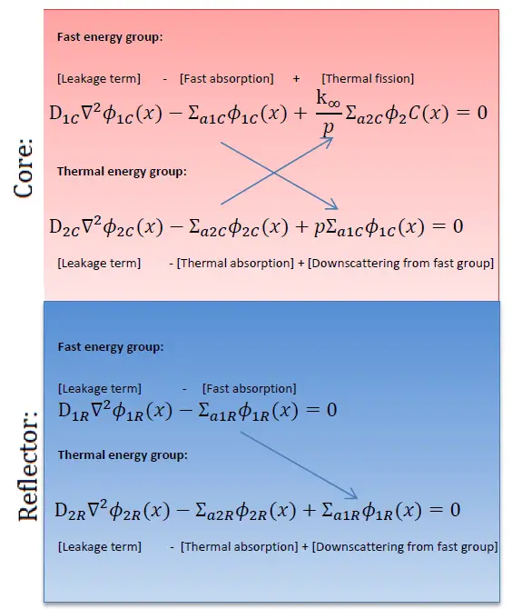
The solution of this system of homogeneous algebraic equations leads to a determinant of the coefficients. Such solution is shown in:
Reference: Ragheb, M. TWO GROUP DIFFUSION THEORY FOR BARE AND REFLECTED REACTORS, University of Illinois, 2006.
One of the striking results of such a solution is that the thermal flux reaches a local maximum near the core-reflector interface. This behavior cannot be derived using the one-group diffusion method because it is caused just by the thermalization of fast neutrons. The fast neutrons produced in the core can enter the reflector at high energy and are not absorbed as quickly in the reflector as neutrons thermalizing in the core because absorption cross-sections in the reflector are much smaller than in the core (due to the absence of fuel). The thermal neutrons accumulate then near the core-reflector interface, resulting in the local maximum, usually known as the reflector peak. This also reduces the non-uniformity of the power distribution in the peripheral fuel assemblies and reduces neutron leakage, i.e., increases keff of the system (or reduces the critical size of the reactor). This effect can be seen in the following figure.
The reflector peak can be seen only in thermal flux within the reflector. It is found that the fast-flux does not show recovery peaks in the reflector but rather drops off sharply inside the reflector (due to thermalization and absorption).

Reflector Savings
The neutron reflector scatters back (or reflects) into the core many neutrons that would otherwise escape. The neutrons reflected back into the core are available for a chain reaction. This means that the minimum critical size of the reactor is reduced. Alternatively, if the core size is maintained, the reflector makes additional reactivity available for higher fuel burnup. The decrease in the critical size of the core required is known as reflector savings. The concept of reflector savings is very important in many reactor calculations.
It can be derived that there is a difference in the reflected and unreflected critical dimensions of a reactor. This difference is known as the reflector savings, it is denoted by δ, and for infinite slab reactor, it is determined by:
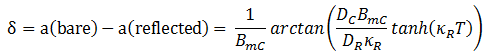
according to this formula, the reflector savings as a function of the reflector thickness T can be calculated. As can be seen, reflector savings are a function of the thickness, and the reflector savings has a finite value for an infinitely thick reflector, where:
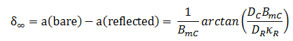
This can be interpreted as follows: when the neutron reflector has a thickness of a few diffusion lengths, the probability that neutrons that have come into the outer shell of the neutron reflector are scattered back to the core is very small, so that an even thicker reflector hardly yields extra savings.
These effects, however, become less significant as the size of the reactor, measured in migration lengths, increases. The reflector savings amounts to a smaller fraction of the core dimension as its size becomes larger.
Adding a reflector to a reactor allows either the volume of the reactor or the requirements on fuel to be reduced or some combination of the two. If the reflector savings is known, the calculation of the critical dimensions of a reflected reactor needs only the solution of the bare reactor, which is a simpler problem. For example, it is only necessary for the cylindrical reactor to determine the bare critical radius R0 and the reflected radius is simply R = R0 – δ, where R0 is the critical diameter of a bare reactor.
Reflector Thickness
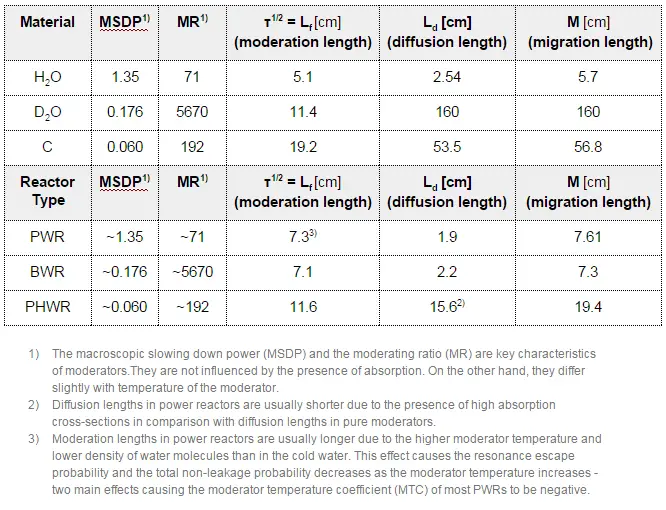
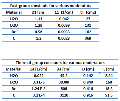
Logically, the reflector coefficient (albedo) increases as the reflector thickness increases. But how thick should a reflector be? From an engineering point of view, reflectors are, of course, limited by certain reactor designs (e.g.,, by the width of the reactor pressure vessel). But, in general, very little is to be gained by increasing the thickness of the reflector beyond a value of 2L (2 x diffusion length).
With H20, a thickness of 2L is only about 5 cm, whereas, for D20, it is about 300 cm. It would require a considerable amount of D20 to extend the moderator by 300 cm since this additional D20 is being placed on the outside of the core. From these values, it is obvious the neutron reflector plays a crucial role in heavy water or graphite reactors, in which the neutron leakage is higher than in LWRs.
Reflector Effects on Reactor Kinetics
Reflector savings are not the only significant effect of the neutron reflector in reactor cores. The neutron reflector also influences the mean generation time and therefore influences the reactor kinetics.
In the effect of a reflector on reactor kinetics, we are concerned with the time the neutrons spend in the reflector before returning to the core. In a thermal reactor, a reflector is generally chosen to help moderate the neutrons. Consequently, the neutrons that leak out of the core as thermal, epithermal, and fast neutrons are reflected back into the core as thermalized neutrons.
Note that the prompt neutron lifetime, l, is the average time from a prompt neutron emission to either its absorption (fission or radiative capture) or its escape from the system. In an infinite reactor (without escape), prompt neutron lifetime is the sum of the slowing downtime and the diffusion time.
l=ts + td
In an infinite thermal reactor ts << td and therefore l ≈ td. The typical prompt neutron lifetime in thermal reactors is on the order of 10−4 seconds. The neutron lifetime with delayed neutrons, ld, is the weighted average of the prompt generation times and a delayed neutron generation time. The delayed neutron generation time, τ, is the weighted average of mean precursor lifetimes of the six groups (or more groups) of delayed neutron precursors.
Because of the time delay in the process of diffusing in and out of the reflector, the kinetics effect of a reflector can be thought of as an effective increase in the neutron lifetime in the core under steady-state conditions or as an additionally delayed neutron precursor under transient operations.