Since spent nuclear fuel is compact, plant operators can store fuel assemblies for a long time. It must be noted that the spent nuclear fuel is due to the presence of a high amount of radioactive fission fragments and transuranic elements that are very hot and very radioactive. Reactor operators must manage the heat and radioactivity in the spent fuel after it’s taken out of the reactor. In nuclear power plants, spent nuclear fuel is stored underwater in the spent fuel pool on the plant. Plant personnel moves the spent fuel underwater from the reactor to the pool. Over time, as the spent fuel is stored in the pool, it becomes cooler as the radioactivity decays away. After several years (> 5 years), decay heat decreases under specified limits so that spent fuel may be reprocessed or interim storage.
Interim Storage and Wait and See
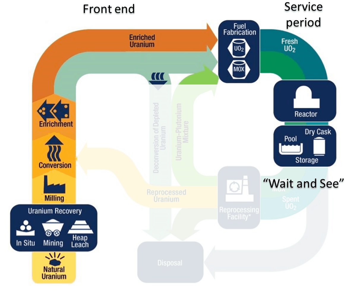
Most countries with nuclear programs use some type of interim storage as their back-end strategy. They have explicitly decided to take a “wait and see” approach to spent fuel management, leaving their spent fuel in interim storage, which leaves both the reprocessing and direct disposal options open for the future. As the name implies, the wait-and-see option proposes interim storage until some solution for permanent storage and disposal is developed in the future. For many operators, the spent fuel also represents a strategic material since the spent nuclear fuel still contains about 96% of reusable material. Storing spent fuel and waste for several years allows heat release and radioactivity to subside. Despite the continued debate over the future of the fuel cycle, a quiet consensus has developed that simply storing spent fuel while developing more permanent solutions is an attractive approach for the near term.
Currently, spent fuel is being stored in at-reactor (AR) or away-from-reactor (APR) storage facilities, and we can identify two basic solutions for interim storage:
- Dry Storage, where natural air circulation dissipates heat.
- Wet Storage, where water is used as the heat conductor.
Dry Storage of Spent Fuel
Dry storage is most often based on the use of spent fuel casks. As its name implies, dry storage of spent fuel assemblies differs from wet storage by using gas or air instead of water as the coolant and metal or concrete instead of water as the radiation barrier. In dry storage systems, sufficiently cooled spent fuel is not stored underwater but loaded in these casks (vaults or silos). If on-site pool storage capacity is exceeded, it may be desirable to store the spent fuel in modular dry storage facilities, which may be at the reactor site (AR) or a facility away from the site (AFR). Spent fuel is transferred from spent fuel pools to thick metal casks or thinner canisters. These casks are then drained, filled with inert gas, and sealed. The thick casks can be placed directly on a concrete pad, while the thinner canisters are placed in concrete casks or vaults to provide radiation shielding. Many regulators have determined that dry storage of spent fuel at reactor sites is safe for at least 100 years and generally consider dry storage safer than pool storage.
Initially, dry storage was a single-purpose system. It only provided storage without the capability or authorization for eventual transport off-site (without rehandling and reloading the fuel into transport casks). Vaults, silos, and non-transportable casks are single-purpose systems. Dual purpose casks were developed, allowing storage and transport to and from a storage facility without rehandling fuel assemblies. The fuel containers of some storage systems may be used for transport and/or final disposal. Dry storage management is less expensive since it provides all safety characteristics, doesn’t need electrical systems (necessary only in vault storage), periodic maintenance, and constant fuel monitoring, increasing the system reliability for longer periods. Because of their inherent flexibility, cask systems have proved popular with reactor operators.
Dry interim storages are practical and approved in many countries, especially that have the “wait and see” philosophy (wait to see new technologies development). It must be added that any strategy for managing spent nuclear fuel will be built around combinations of many options, and all strategies must ultimately include permanent geological disposal.
Spent Fuel Cask – Dry Storage Cask
Dry storage casks or canisters are widely used for dry interim storage and transportation of spent nuclear fuel. They can be oriented and stored vertically or horizontally. The casks provide both shielding and containment. The casks are typically steel cylinders that are either welded or bolted closed. The steel cylinder provides leak-tight containment of the spent fuel. Each cylinder is surrounded by additional steel, concrete, or other material to shield workers and the public from radiation. This additional material is a barrier preventing physical damage that might result in a release of radiation.
- Metal Casks. Metal casks are massive containers used to transport, store, and dispose of spent fuel. These casks usually consist of a monolithic body made of ductile cast iron, a basket for accommodating the fuel assemblies, and a double-lid system (primary and secondary lid arranged one above the other). An internal basket or sealed metal canister provides structural strength and assures subcriticality.
- Concrete Casks. Concrete casks have the same inner disposition that a metallic cask has. Spent fuel assemblies are distributed in internal baskets inserted into these containers. But structural strength and radiological shielding are provided by reinforced regular or high-density concrete. Concrete is neutrons and gamma radiation shielding. Generally, concrete casks are heavier than metallic ones since their wall thickness is greater and are less expensive than metallic ones. Concrete casks that rely on conductive heat transfer have more thermal limitations than those using natural convection air passages.
Some of the cask designs can be used for both storage and transportation. These dual-purpose casks were developed, allowing storage and transport to and from a storage facility without rehandling fuel assemblies. The fuel containers of some storage systems may be used for transport and/or final disposal (multipurpose casks). Spent fuel is transferred underwater from spent fuel pools to these casks using primarily fuel handling equipment already available at the reactor site. These casks are then drained, filled with inert gas, and sealed. The external surface of the cask has trunnions that allow the cask to be lifted and displaced. Shock absorbers of the cask installed at the bottom and the cover assure transport stability.
During interim storage, the lid system consisting of the two barriers is permanently monitored for leak-tightness. The radiation emitted by the radioactive inventory is safely shielded by the cask body. For neutron moderation, axial boreholes are drilled into the monolithic body and filled with polyethylene moderator rods.
The operations often occur in the same space and use the same equipment meaning the vast majority of steps must be completed sequentially, and dry storage casks cannot be loaded in parallel. Sometimes, dry storage casks use the same lifting equipment (polar crane) as other outage activities, extending plant outage. The main steps to load a cask are performed as follows:
- Preparation of a cask for fuel loading
- Transfer the cask into the spent fuel pool
- Load fuel into the
- Remove the loaded cask from the spent fuel pool
- Decontaminate cask exterior
- Drain a small amount of water from the cask cavity, then weld/bolt and inspect the inner lid (vacuum or forced helium drying system)
- Transfer the cask from the plant to the storage facility
- Store cask
Safety of Spent Fuel Casks
The safety of spent fuel casks stands on various criteria. These criteria may be grouped according to the following aspects:
- Subcriticality. Fulfillment of this criterion is based on:
- the design of the spent fuel cask,
- requirements on materials of the spent fuel casks ( e.g., adding neutron absorbing materials (typically boron) in storage racks baskets),
- limiting of stored fuel (e.g., fuel enrichment, assembly burnup)
- Cooling. Fulfillment of this criterion is based on:
- the design of the spent fuel cask (e.g., shape and orientation of cooling fins),
- requirements on inert gas pressure,
- Radiation Shielding. Fulfillment of this criterion is based on:
- the design of the spent fuel cask (e.g., wall thickness),
- neutron shielding (polyethylene moderator rods)
- Integrity. Fulfillment of this criterion is based on:
- the design of the spent fuel cask,
- the design of shock absorbers,
- ensuring periodic inspections
These goals are not difficult to achieve. Very few scenarios can be imagined in dry cask storage that could provide the energy needed to break the cask and spread the radioactive material into the surrounding environment. Because of their inherent flexibility, cask systems have proved popular with reactor operators.
Dry Storage Vaults
In a dry storage vault, the spent fuel is stored in a reinforced concrete building, whose exterior structure serves as the radiation barrier and whose interior has large numbers of cavities suitable for spent fuel storage units. These cavities contain metallic cylinders in which external air is insufflated, or sometimes the air circulation is natural. Spent fuel is received (either dry or wet) at a vault facility using transfer or transportation casks. The fuel is typically stored in sealed metal storage tubes or storage cylinders, which may hold one or several fuel assemblies. These cylinders contain the radioactive material in the spent fuel, and shielding is provided by the exterior structure. Heat removal is normally accomplished by forced or natural convection of air or gas over the exterior of the fuel-containing units or storage cavities and subsequently exhausting this air directly to the outside atmosphere or dissipating the heat via a secondary heat removal system.
Thus, vault systems typically also require cranes or fuel-handling machines. Typical features of vaults are their modularity, which facilitates incremental capacity extension, separated shielding and containment functions, capability for containment monitoring, and a vertical fuel loading methodology.
Dry Storage Silos
In s dry storage silo system, the spent nuclear fuel is stored in metallic canisters inside a concrete cylinder on the floor (silos). Silos are monolithic or modular concrete reinforced structures that provide radiation shielding (as the building exterior does in the case of a vault). In contrast, the sealed inner metal liner or canister provides containment. The storage position can be vertical or horizontal. Spent fuel is received (either dry or wet) at a vault facility using transfer or transportation casks. Canisters are then loaded into silos. Concrete is the structural material and the radiation shielding (like the building in vault storage), as the canisters provide containment. Heat is removed by air convection through ducts in the concrete cylinders. The metal canisters are also fitted with a double lid closure system, which, following welding, is tested for leak tightness.
Wet Storage of Spent Fuel
Currently, spent fuel is being stored in at-reactor (AR) or away-from-reactor (AFR) storage facilities, and we can identify two basic solutions for interim storage:
- Dry Storage, where natural air circulation dissipates heat.
- Wet Storage, where water is used as the heat conductor.

Wet storage of spent nuclear fuel in wet storage pools is a common practice worldwide. It is very similar to at-reactor spent fuel storage, but in this case, storage facilities are usually for many power plants. Irradiated fuel is due to the presence of a high amount of radioactive fission fragments and transuranic elements that are very hot and very radioactive. Reactor operators must manage the heat and radioactivity that remains in the “spent fuel” after it’s taken out of the reactor. In nuclear power plants, spent nuclear fuel is stored underwater in the spent fuel pool on the plant. Plant personnel moves the spent fuel underwater from the reactor to the pool. Over time, as the spent fuel is stored in the pool, it becomes cooler as the radioactivity decays away. After several years (> 5 years), decay heat decreases under specified limits so that spent fuel may be reprocessed or interim storage. Many regulators have determined that dry storage of spent fuel at reactor sites is safer than wet storage. True AFR storage pools are independent of the reactor and all its services and can continue to operate after the reactor has been finally shut down and decommissioned. Centralized interim storage does not eliminate the need for developing a long-term disposal option, but it might provide other benefits.
A typical wet storage facility may have the following features:
- Cask reception, decontamination, unloading, maintenance, and dispatch
- Underwater spent fuel storage (pool);
- Auxiliary services (radiation monitoring, water cooling and purification, solid radioactive waste handling, ventilation, power supply, etc.).
Spent fuel pools are fitted with stainless steel and aluminum racks that hold the fuel assemblies and are lined with stainless steel to prevent leaking. No drains would allow the water level to drop or the pool to become empty. The plants have a variety of extra water sources and equipment to replenish the water that evaporates over time or in case of a leak. Plant personnel is also trained and prepared to respond to a problem quickly. The water serves two purposes: it cools the fuel and shields workers at the plant from radioactivity. Although water is neither high density nor high Z material, it is commonly used as a gamma shield. Water provides a radiation shielding of fuel assemblies in a spent fuel pool during storage or transport from and into the reactor core. Although water is a low-density material and low Z material, it is commonly used in nuclear power plants because these disadvantages can be compensated with increased thickness.
To conserve space, in all plants, open storage racks were replaced with so-called high-density racks that incorporate (boron-10) or other neutron-absorbing material to ensure subcriticality. Fuel assemblies can be stored in about one-half the volume required for storage in standard racks using such racks.
Safety of Spent Fuel Pool
The safety of AFR spent fuel pools stands on various criteria. These criteria are usually very similar to the criteria for AR pools and may be grouped according to the following aspects:
- Subcriticality. Fulfillment of this criterion is based on:
- the design of the spent fuel pool,
- requirements on boric acid diluted in water,
- limiting of stored fuel (e.g., fuel enrichment, assembly burnup)
- Cooling. Fulfillment of this criterion is based on:
- the design of the spent fuel pool (e.g., no drains below the top of the stored fuel elements),
- requirements on the water level in the pool,
- requirements on active cooling elements (heat exchangers and heat sink).
- Radiation Shielding. Fulfillment of this criterion is based on:
- the design of the spent fuel pool (water and concrete shielding),
- the design of the surrounding working area
- requirements on the water level in the pool,
- Integrity. Fulfillment of this criterion is based on:
- the design of the spent fuel pool,
- the design of the surrounding working area,
- ensuring periodic inspections