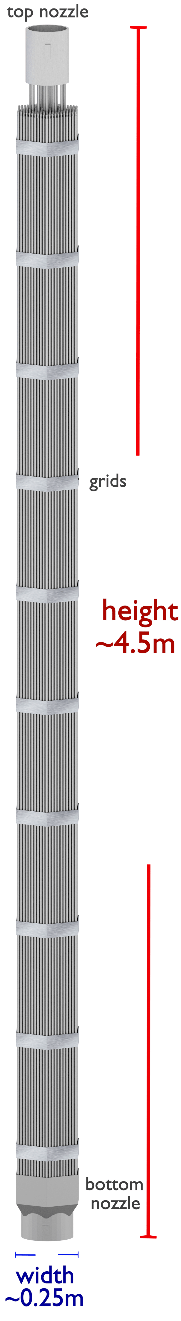
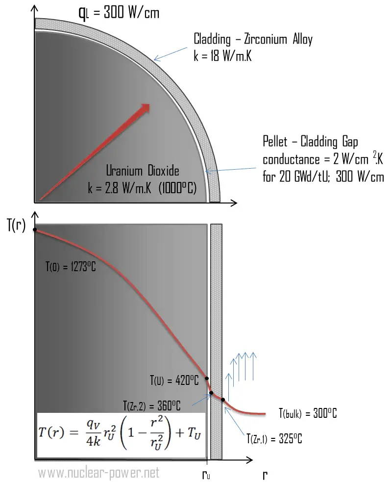
Fuel rods are the base element of a fuel assembly. Fuel rods have the purpose of containing fission products, ensuring mechanical support for the pellets, and allowing the heat removal to the coolant fluid of the heat generated by nuclear reactions. A typical fuel rod has a length of some 4 m, with a diameter of around 1 cm. Fuel rods are made of zirconium alloy (e.g., Zr + 1%Nb), widely used as a cladding for nuclear reactor fuels. The desired properties of these alloys are a low neutron-capture cross-section and resistance to corrosion under normal service conditions. Zirconium alloys have lower thermal conductivity (about 18 W/m.K) than pure zirconium metal (about 22 W/m.K).
Fuel rods contain fuel pellets, which are then loaded and encapsulated within a fuel rod. Aside from the stacked pellets and cladding tube, the rod comprises two welded end plugs, a plenum (or expansion chamber) to accommodate the fission gases released, and a spring located inside the plenum, holding the fuel column in position. The fuel rod is filled with helium at a pressure of about 25 bars to compensate, in part, for the outside pressure, in the primary circuit (155 bars in PWRs).
A PWR fuel assembly comprises a bottom nozzle into which rods are fixed through the lattice, and it is ended by a top nozzle to finish the whole assembly. There are spacing grids between these nozzles, which ensure the fuel rods’ exact guiding. The bottom and top nozzles are heavily constructed as they provide much mechanical support for the fuel assembly structure. The top nozzle ensures the assembly handling function. Spacing grids are welded onto the guide tubes and ensured, using springs and dimples, fuel rod support, and spacing. They may carry vanes, allowing improved mixing of fluid streams, thus enhancing the assembly’s thermal-hydraulic performance.
Western PWRs use a square lattice arrangement, and assemblies are characterized by the number of rods they contain, typically 17×17 in current designs. The enrichment of fuel rods is never uniform, and the enrichment is differentiated in the radial and axial directions. This arrangement improves power distribution and improves fuel economy.
Russian VVER-type reactors use a fuel characterized by their hexagonal arrangement but is otherwise of similar length and structure to other PWR fuel assemblies.
Zirconium Alloy
A typical composition of nuclear-grade zirconium alloys is more than 95 weight percent zirconium and less than 2% of tin, niobium, iron, chromium, nickel, and other metals added to improve mechanical properties and corrosion resistance. To date, the most commonly used alloy in PWRs has been Zircaloy 4. However, currently, this is being replaced by new zirconium–niobium-based alloys, exhibiting better corrosion resistance. The maximum temperature at which zirconium alloys can be used in water-cooled reactors depends on their corrosion resistance. Alloys of type Zircalloy, in which tin is the basic alloying element that improves their mechanical properties, have a wide distribution worldwide. However, in this case, the corrosion resistance in water and steam is decreased, resulting in the need for additional alloying. The improvement brought about by the additive niobium probably involves a different mechanism. The high corrosion resistance of niobium alloyed metals in water and steam at temperatures of 400–550°C is caused by their ability to passivation with the formation of protective films.
Temperature Profile – Fuel Pellets
See also: Temperature Profile – Calculation
See also: Cladding Surface Temperature
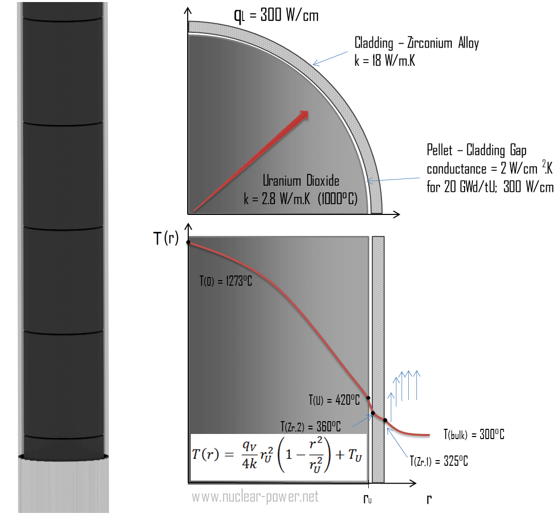
Consider the fuel cladding of inner radius rZr,2 = 0.408 cm and outer radius rZr,1 = 0.465 cm. Compared to fuel pellet, there is almost no heat generation in the fuel cladding (cladding is slightly heated by radiation). All heat generated in the fuel must be transferred via conduction through the cladding. Therefore, the inner surface is hotter than the outer surface.
We must solve the heat conduction equation to find the temperature distribution through the cladding. Due to symmetry in the z-direction and azimuthal direction, we can separate variables and simplify this problem to a one-dimensional problem. Thus, we will only solve for the temperature as a function of radius, T(r). In this example, we will assume that there is strictly no heat generation within the cladding. For constant thermal conductivity, k, the appropriate form of the cylindrical heat equation, is:
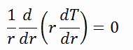
The general solution of this equation is:

where C1 and C2 are the constants of integration.
1)
 Calculate the temperature distribution, T(r), in this fuel cladding, if:
- the temperature at the inner surface of the cladding is TZr,2 = 360°C
- the temperature of reactor coolant at this axial coordinate is Tbulk= 300°C
- the heat transfer coefficient (convection; turbulent flow) is h = 41 kW/m2.K.
- the averaged material’s conductivity is k = 18 W/m.K
- the linear heat rate of the fuel is qL = 300 W/cm, and thus the volumetric heat rate is qV = 597 x 106 W/m3
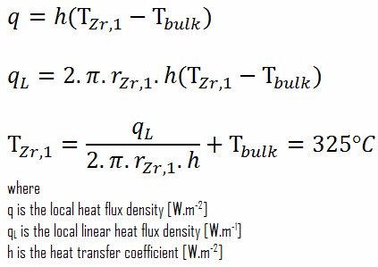
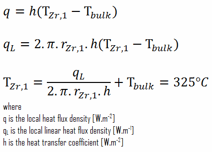
From the basic relationship for heat transfer by convection, we can calculate the outer surface of the cladding as:
As can be seen, in this case, we have given surface temperatures TZr,1 and TZr,2. This corresponds to the Dirichlet boundary condition. The constants may be evaluated using substitution into the general solution and are of the form:

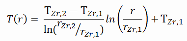
Solving for C1 and C2 and substituting them into the general solution, we then obtain:
∆T – cladding surface – coolant
Detailed knowledge of geometry, the outer radius of cladding, linear heat rate, convective heat transfer coefficient, and the coolant temperature determines ∆T between the coolant (Tbulk) and the cladding surface (TZr,1). Therefore we can calculate the cladding surface temperature (TZr,1) simply using Newton’s Law:
∆T in fuel cladding
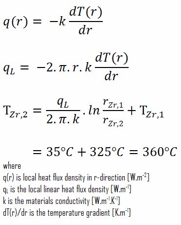
Detailed knowledge of geometry, outer and inner radius of cladding, linear heat rate, and the cladding surface temperature (TZr,1) determine ∆T between outer and inner surfaces of cladding. Therefore we can calculate the inner cladding surface temperature (TZr,2) simply using Fourier’s Law: