Pressure-Suppression Systems
The containment building is primarily designed to prevent or mitigate the uncontrolled release of radioactive material to the environment in operational states and accident conditions. Therefore it is considered to be the fourth and final barrier in the in-depth Defence strategy.
While the containment plays a crucial role in Design Basis Accidents or Design Extension conditions, it is “only” designed to condense steam from primary coolant and contain it inside the building.
In case of Design Basis Accidents such as the Large Break Loss of Coolant Accident (LBLOCA), the pressure increase is usually significant, and active containment systems (pressure-suppression systems) must be available to maintain the integrity (to keep the pressure and temperature under certain limits) of the containment building. Pressure-suppression systems are critical to safety and greatly affect the size of containment. Suppression refers to condensing the steam after a major break has released it from the cooling system. There are many designs of suppression systems around the world.
Most Pressurized Water Reactors (PWRs) containments use two-stage pressure-suppression systems:
- Fan Cooler System. This system circulates air through heat exchangers and filters to provide the cooling of containment atmosphere. Since this system is insufficient for suppression during a severe loss of coolant accidents, the containment spray system must be available as the secondary active pressure suppression system.
- Containment Spray System. This system usually consists of three elements:
- Spray System Pump
- Spray System Tank
- Spray System Rings and Nozzles
When pressure increase inside the containment is indicated, the containment spray system is automatically started, and the pumps (usually with 3×100% redundancy) take suction from the tank (refueling water storage tank can also be used) and pump the water into spray nozzles located in the upper part of the containment. The water droplets, being cooler than the steam, will remove heat from the steam, which will cause the steam to condense. This will cause a reduction in the pressure of the building and will also reduce the temperature of the containment atmosphere.
The spray system usually contains extra chemical additives dissolved in the tank to enhance the removal of particular radionuclides from the containment atmosphere. Especially radioiodine, which is important, can be effectively bonded to potassium hydroxide or sodium hydroxide.
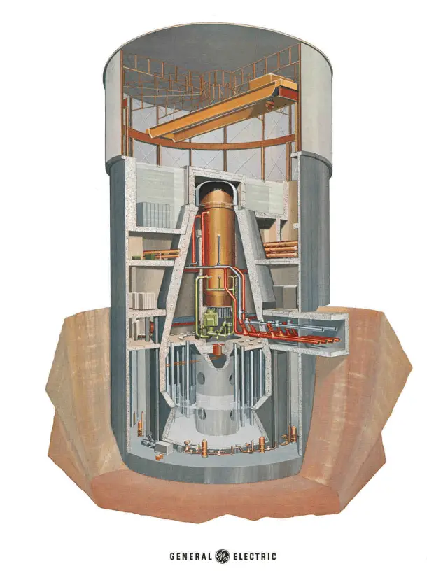
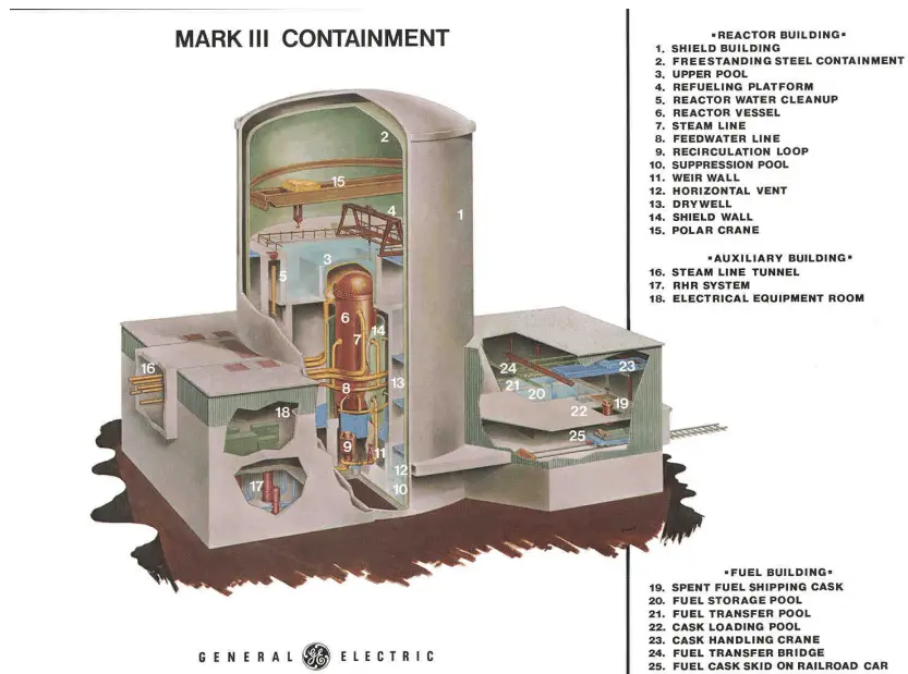
Most Boiling Water Reactors (BWR) containments use pressure-suppression pools to maintain the integrity of the containment building. The major containment designs are Mark I, Mark II, and Mark III. Mark I and Mark II containments consist of two main parts:
- Drywell. A drywell houses the reactor coolant system.
- Wetwell. A wetwell is a suppression chamber, which stores a large body of water, and therefore it is commonly called the suppression pool.
Water spray systems are usually installed in both the drywell and the wetwell. The Mark III design consists of primary containment and a drywell. Containment buildings and containment pressure-suppression systems vary widely depending on certain reactor designs. In some cases, unique technologies can be installed. For example, the containment building of Loviisa NPP uses two ice condensers as the pressure-suppression system.
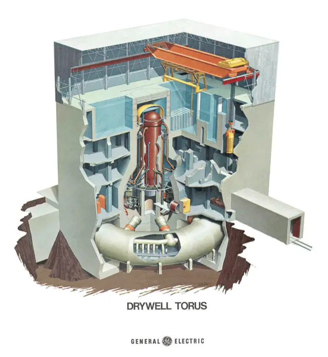
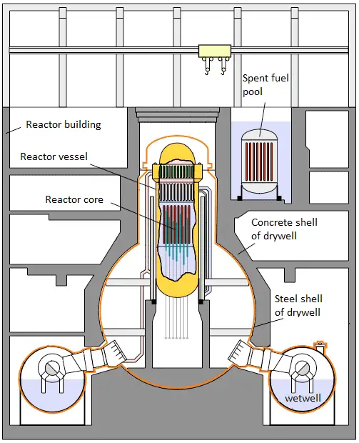 Containment building BWR Mark-I. A drywell houses the reactor coolant system. A wetwell is a suppression chamber, which stores a large body of water.