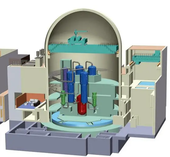
The containment building is a gas-tight (shell) or other enclosure around a nuclear reactor and a primary circuit. The Containment is the most characteristic structure of a nuclear power plant. Practically all nuclear power plants built during the last few decades include a containment building.
The containment building should be designed to ensure or contribute to the achievement of the following safety functions:
- Confinement. Confinement of radioactive material in operational states and accident conditions.
- Protection. Protection of the power plant against external natural and human-induced events
- Shielding. Radiation shielding in operational states and accident conditions.
While the Containment plays a crucial role in Design Basis Accidents or Design Extension conditions, it is “only” designed to condense steam from primary coolant and contain it inside the building.
In case of Design Basis Accidents such as the Large Break Loss of Coolant Accident (LBLOCA), the pressure increase is usually significant, and active containment systems (pressure-suppression systems) must be available to maintain the integrity (to keep the pressure and temperature under certain limits) of the containment building.
Pressure-Suppression Systems
Pressure-suppression systems are critical to safety and greatly affect the size of Containment. Suppression refers to condensing the steam after a major break has released it from the cooling system. There are many designs of suppression systems around the world.
Most Pressurized Water Reactors (PWRs) containments use two-stage pressure-suppression systems:
- Fan Cooler System. This system circulates air through heat exchangers and filters to provide the cooling of containment atmosphere. Since this system is insufficient for suppression during a severe loss of coolant accidents, the containment spray system must be available as the secondary active pressure suppression system.
- Containment Spray System. This system consist usually of three elements:
- Spray System Pump
- Spray System Tank
- Spray System Rings and Nozzles
When pressure increase inside the Containment is indicated, the containment spray system is automatically started, and the pumps (usually with 3×100% redundancy) take suction from the tank (refueling water storage tank can also be used) and pump the water into spray nozzles located in the upper part of the Containment. The water droplets, being cooler than the steam, will remove heat from the steam, which will cause the steam to condense. This will cause a reduction in the pressure of the building and will also reduce the temperature of the containment atmosphere. The spray system usually contains extra chemical additives dissolved in the tank to enhance the removal of particular radionuclides from the containment atmosphere. Especially radioiodine, which is important, can be effectively bonded to potassium hydroxide or sodium hydroxide.
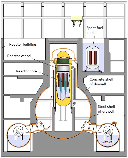
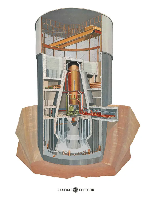
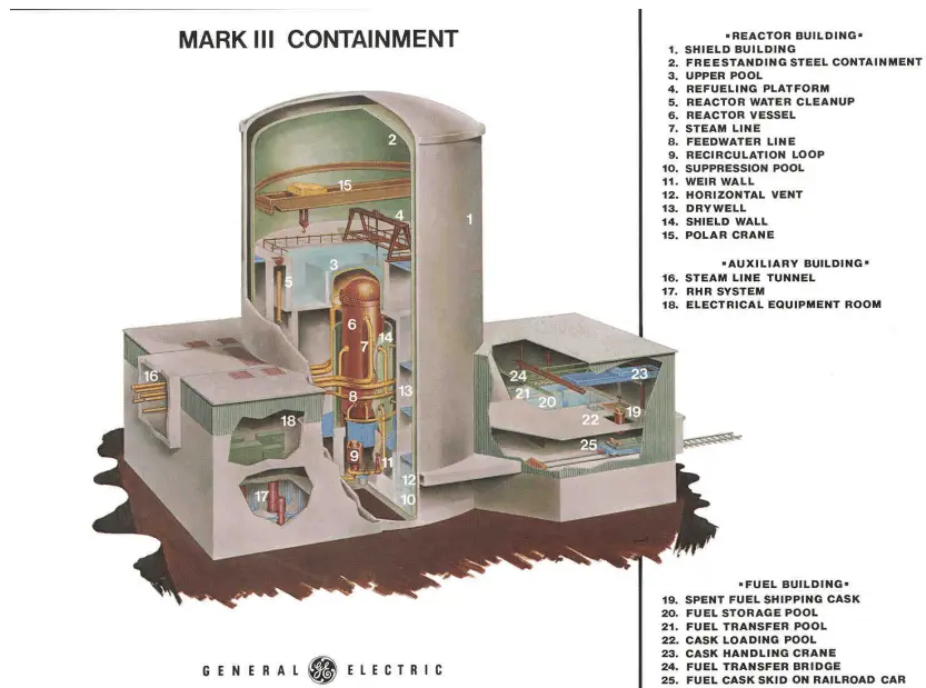
Most Boiling Water Reactors (BWR) containments use pressure-suppression pools to maintain the integrity of the containment building. The major containment designs are the Mark I, Mark II, and Mark III. The Mark I and Mark II containments consist of two main parts:
- Drywell. A drywell houses the reactor coolant system.
- Wetwell. A wetwell is a suppression chamber, which stores a large body of water, and therefore it is commonly called the suppression pool.
Water spray systems are usually installed in both the drywell and the wetwell. The Mark III design consists of primary Containment and a drywell.
Containment buildings and containment pressure-suppression systems vary widely depending on certain reactor designs. In some cases, unique technologies can be installed. For example, the containment building of Loviisa NPP uses two ice condensers as the pressure-suppression system.
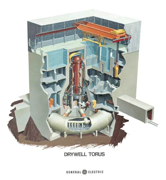
 Containment building BWR Mark-I. A drywell houses the reactor coolant system. A wetwell is a suppression chamber, which stores a large body of water.
Ice Condenser Containment Building
The ice condenser is a safety system designed to rapidly absorb steam and reduce containment pressure following a Loss of Coolant Accident (LOCA) or Main Steam Line Break (MSLB). The high-pressure steam following LOCA or MSLB conditions is directed into chambers containing baskets filled with ice. Ice blocks, being naturally cooler than the steam, will remove heat from the steam, which will cause the steam to condense. This will cause a reduction in the pressure of the building and will also reduce the temperature of the containment atmosphere.
This system has many positive features. Pressure suppression via ice condensers is very effective because of the ability of ice to absorb a high amount of energy during a phase transition. This feature allows containment building to be much smaller than conventional containment buildings. Moreover, water from ice melting can be used for passive cooling and flooding of the small-sized cavity (in the case of Loviisa NPP), where the reactor is located.
Westinghouse designed ice condenser containments in the late 1970s and early 1980s, therefore in the United States, there are 9 ice condenser containments on 5 sites. Except for Loviisa NPP, there is one other ice condenser unit globally, the Ohi plant in Japan.
Hydrogen Mitigation in Water Cooled Power Reactors
Hydrogen mitigation in water-cooled power reactors is an important area of study in the field of safety of nuclear reactors. Hydrogen and oxygen can be generated during the normal operation of a power reactor primarily due to the radiolysis of the water in the core.
During accidents, hydrogen and oxygen can also be generated as a consequence of:
- Metal–water reactions in the core
- Radiolysis of the water in the sump or the suppression pool
- Degassing of hydrogen dissolved in the primary coolant
- Chemical reactions with materials in the Containment ( interactions of molten core debris with concrete)
- Thermolysis of water – in extreme cases
During DBAs (Design Basis Accidents) such as the large break loss of coolant accident, the production of hydrogen (metal–water reactions in the core) is limited at low values by the operation of the emergency core cooling systems. Also, the radiolysis of the water in the core is a relatively slow process. Therefore, from the DBAs point of view, the hydrogen hazards can be eliminated by maintaining the local hydrogen concentration below its flammability limit (4% of volume). This requirement can be ensured by mixing devices or thermal hydrogen recombiners.
In the past two decades, research activities to analyze the threat of hydrogen in a post-accident condition have focused mainly on mitigating hydrogen hazards in severe accidents. In severe accidents, consider the possibility of large-scale core degradation and even the possibility of molten core concrete interactions.
For these cases, the capacity of conventional DBA hydrogen control is insufficient. During severe accidents, local hydrogen concentrations can exceed their flammability limit in a short time. Analysis of the hydrogen threat in post-accident containments is complex and highly plant- and scenario-specific.
Mitigation measures for hydrogen in severe accidents must be implemented to avoid the threat of hydrogen explosion. The strategy is usually based on the following physical principles:
- Avoiding of formation of flammable mixtures by oxygen control.
- Avoiding of formation of flammable mixtures by hydrogen control
- Avoiding flammable or detonable concentrations of hydrogen by controlled ignition.
The most effective measures are:
- Passive or active air mixing systems.
- Post-accident dilution (PAD) of containment atmosphere by inert gas injection.
- Catalytic recombination of hydrogen.
- Controlled ignition by deliberated ignition system (DIS).