Source: wikipedia.org CC BY-SA
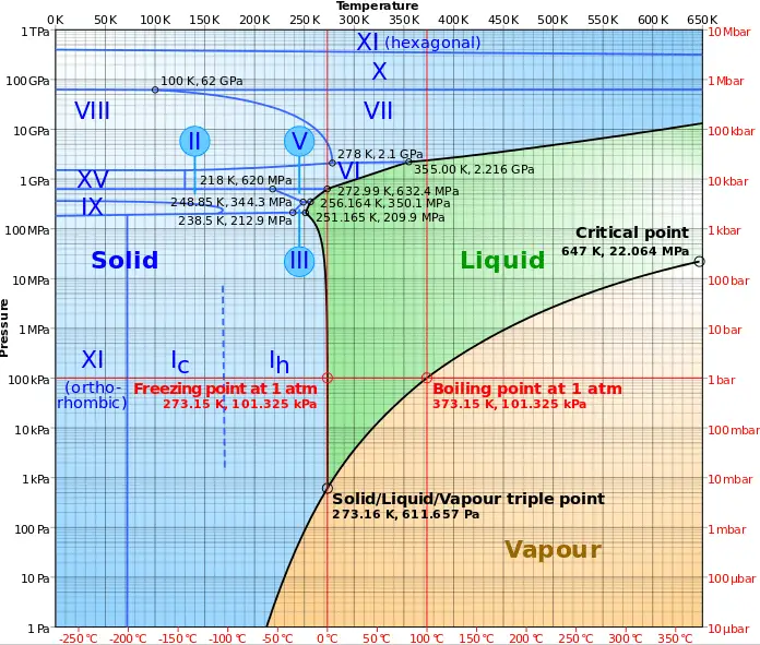
As seen from the phase diagram of water, in the two-phase regions (e.g.,, on the border of vapor/liquid phases), specifying temperature alone will set the pressure, and specifying pressure will set the temperature.
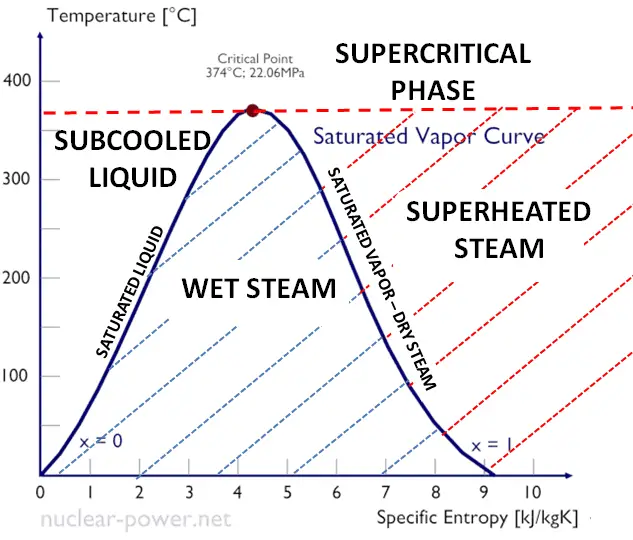
- The saturation vapor curve separates the two-phase state and the superheated vapor state in the T-s diagram.
- The saturated liquid curve separates the subcooled liquid state and the two-phase state in the T-s diagram.
If steam exists entirely as vapor at saturation temperature, it is called saturated vapor, saturated steam, or dry steam. The dry saturated vapor is characterized by the vapor quality, which is equal to unity. Superheated vapor or superheated steam is a vapor at a temperature higher than its boiling point at the absolute pressure where the temperature is measured. The pressure and temperature of superheated vapor are independent properties since the temperature may increase while the pressure remains constant. The substances we call gases are highly superheated vapors.
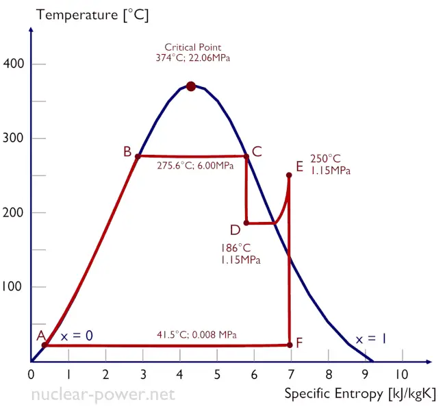
The process of superheating water vapor in the T-s diagram is provided in the figure between state E and the saturation vapor curve. As can be seen, also wet steam turbines use superheated steam, especially at the inlet of low-pressure stages. The enthalpy must be obtained from the superheated steam tables to evaluate the cycle thermal efficiency.
The superheating process is the only way to increase the peak temperature of the Rankine cycle (and to increase efficiency) without increasing the boiler pressure. This requires the addition of another type of heat exchanger called a superheater, which produces the superheated steam.
In the superheater, further heating at fixed pressure results in increases in both temperature and specific volume. The process of superheating in the T-s diagram is provided in the figure between state E and the saturation vapor curve.
Typically most nuclear power plants operate multi-stage condensing steam turbines. In these turbines, the high-pressure stage receives steam (this steam is nearly saturated steam – x = 0.995 – point C at the figure) from a steam generator and exhausts it to a moisture separator-reheater (point D). The steam must be reheated or superheated to avoid damages caused to the blades of the steam turbine by low-quality steam. The high content of water droplets can cause rapid impingement and erosion of the blades, which occurs when condensed water is blasted onto the blades. To prevent this, condensate drains are installed in the steam piping leading to the turbine. The reheater heats the steam (point D), and then the steam is directed to the low-pressure stage of the steam turbine, where it expands (point E to F). The exhausted steam is well below atmospheric pressure and is in a partially condensed state (point F), typically of a quality near 90%.

A pressurizer is a component of a pressurized water reactor. Pressure in the primary circuit of PWRs is maintained by a pressurizer, a separate vessel connected to the primary circuit (hot leg), and partially filled with water heated to the saturation temperature (boiling point) for the desired pressure by submerged electrical heaters. The temperature in the pressurizer can be maintained at 350 °C (662 °F), which gives a subcooling margin (the difference between the pressurizer temperature and the highest temperature in the reactor core) of 30 °C. Subcooling margin is a very important safety parameter of PWRs since the boiling in the reactor core must be excluded. The basic design of the pressurized water reactor includes such a requirement that the coolant (water) in the reactor coolant system must not boil. To achieve this, the coolant in the reactor coolant system is maintained at a pressure sufficiently high that boiling does not occur at the coolant temperatures experienced while the plant is operating or in an analyzed transient.
Functions
Pressure in the pressurizer is controlled by varying the temperature of the coolant in the pressurizer. For these purposes, two systems are installed. Water spray system and electrical heaters system. The volume of the pressurizer (tens of cubic meters) is filled with water on saturation parameters and steam. The water spray system (relatively cool water – from the cold leg) can decrease the pressure in the vessel by condensing the steam on water droplets sprayed in the vessel. On the other hand, the submerged electrical heaters are designed to increase the pressure by evaporating the water in the vessel. Water pressure in a closed system tracks water temperature directly; as the temperature rises, the pressure goes up.
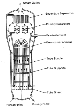
Steam generators are heat exchangers that convert feedwater into steam from heat produced in a nuclear reactor core. The steam produced drives the turbine. They are used in most nuclear power plants, but there are many types according to the reactor type.
The hot primary coolant (water 330°C; 626°F; 16MPa) is pumped into the steam generator through the primary inlet. High pressure of primary coolant is used to keep the water in the liquid state. Boiling of the primary coolant shall not occur. The liquid water flows through hundreds or thousands of tubes (usually 1.9 cm in diameter) inside the steam generator. The feedwater (secondary circuit) is heated from ~260°C 500°F to the boiling point of that fluid (280°C; 536°F; 6,5MPa). Heat is transferred through the walls of these tubes to the lower pressure secondary coolant located on the secondary side of the exchanger where the coolant evaporates to pressurized steam (saturated steam 280°C; 536°F; 6,5 MPa). The pressurized steam leaves the steam generator through a steam outlet and continues to the steam turbine. Heat transfer is accomplished without mixing the two fluids to prevent the secondary coolant from becoming radioactive. The primary coolant leaves (water 295°C; 563°F; 16MPa) the steam generator through the primary outlet and continues through a cold leg to a reactor coolant pump and then into the reactor.
Vapor Quality – Dryness Fraction
 As seen from the phase diagram of water, in the two-phase regions (e.g.,, on the border of vapor/liquid phases), specifying temperature alone will set the pressure, and specifying pressure will set the temperature. But these parameters will not define the volume and enthalpy because we will need to know the relative proportion of the two phases present.
The mass fraction of the vapor in a two-phase liquid-vapor region is called the vapor quality (or dryness fraction), x, and it is given by the following formula:
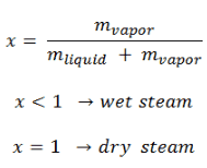
The value of the quality ranges from zero to unity. Although defined as a ratio, the quality is frequently given as a percentage. From this point of view, we distinguish between three basic types of steam. It must be added, at x=0, we are talking about the saturated liquid state (single-phase).
This classification of steam has its limitation. Consider the system’s behavior, which is heated at a pressure that is higher than the critical pressure. In this case, there would be no change in phase from liquid to steam. In all states, there would be only one phase. Vaporization and condensation can occur only when the pressure is less than the critical pressure. The terms liquid and vapor tend to lose their significance.
See also: Saturation
Properties of Steam – Steam Tables
Water and steam are common fluids used for heat exchange in the primary circuit (from the surface of fuel rods to the coolant flow) and in the secondary circuit. It is used due to its availability and high heat capacity, both for cooling and heating. It is especially effective to transport heat through vaporization and condensation of water because of its very large latent heat of vaporization.
A disadvantage is that water-moderated reactors have to use the high-pressure primary circuit to keep water in the liquid state and achieve sufficient thermodynamic efficiency. Water and steam also react with metals commonly found in industries such as steel and copper, oxidized faster by untreated water and steam. In almost all thermal power stations (coal, gas, nuclear), water is used as the working fluid (used in a closed-loop between boiler, steam turbine, and condenser), and the coolant (used to exchange the waste heat to a water body or carry it away by evaporation in a cooling tower).
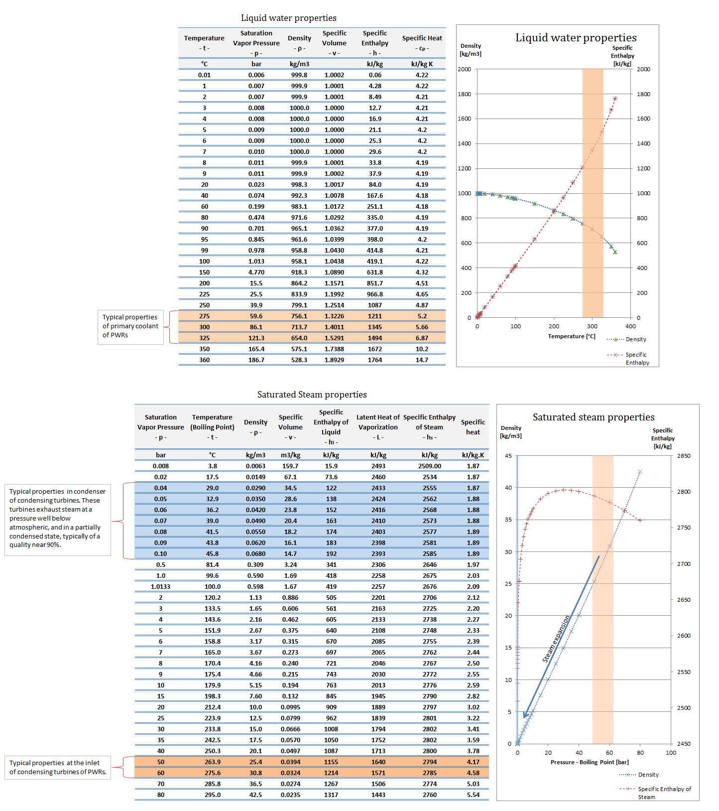
Water and steam are common medium because their properties are very well known. Their properties are tabulated in so-called “Steam Tables”. In these tables, the basic and key properties, such as pressure, temperature, enthalpy, density, and specific heat, are tabulated along the vapor-liquid saturation curve as a function of both temperature and pressure. The properties are also tabulated for single-phase states (compressed water or superheated steam) on a grid of temperatures and pressures extending to 2000 ºC and 1000 MPa.
Further comprehensive, authoritative data can be found at the NIST Webbook page on thermophysical properties of fluids.
See also: Steam Tables.
Special Reference: Allan H. Harvey. Thermodynamic Properties of Water, NISTIR 5078. Retrieved from https://www.nist.gov/sites/default/files/documents/srd/NISTIR5078.htm

Source: wikipedia.org CC BY-SA