It is one of the most important/useful equations in fluid mechanics. It puts into a relation pressure and velocity in an inviscid incompressible flow. Bernoulli’s effect causes the lowering of fluid pressure (static pressure – p) in regions where the flow velocity increases. The Bernoulli equation can be modified to take into account gains and losses of the head. The resulting equation referred to as the extended Bernoulli’s equation is useful in solving most fluid flow problems.
Bernoulli’s equation has some restrictions in its applicability, they summarized in the following points:
- steady flow system,
- density is constant (which also means the fluid is incompressible),
- no work is done on or by the fluid,
- no heat is transferred to or from the fluid,
- no change occurs in the internal energy,
- the equation relates the states at two points along a single streamline (not conditions on two different streamlines)
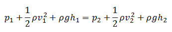
Under these conditions, the general energy equation is simplified to:
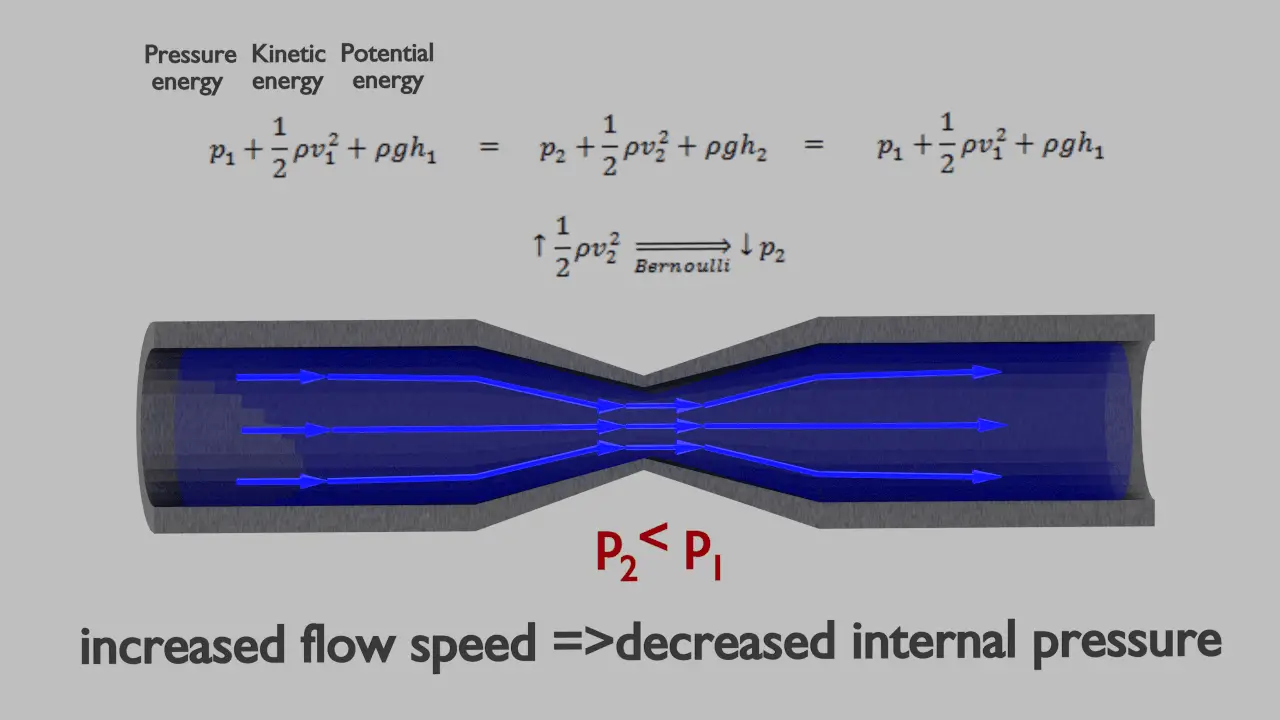
This equation is the most famous equation in fluid dynamics. Bernoulli’s equation describes the qualitative behavior flowing fluid that is usually labeled with the term Bernoulli’s effect. This effect causes the lowering of fluid pressure in regions where the flow velocity is increased. This lowering of pressure in a constriction of a flow path may seem counterintuitive but seems less so when you consider the pressure to be energy density. In the high-velocity flow through the constriction, kinetic energy must increase at the expense of pressure energy. The dimensions of terms in the equation are kinetic energy per unit volume.
Static pressure is one of the terms of Bernoulli’s equation:
Bernoulli’s effect causes the lowering of fluid pressure (static pressure – p) in regions where the flow velocity increases. This lowering of pressure in a constriction of a flow path may seem counterintuitive but seems less so when you consider the pressure to be energy density. In the high-velocity flow through the constriction, kinetic energy (dynamic pressure – ½.ρ.v2) must increase at the expense of pressure energy (static pressure – p).
The simplified form of Bernoulli’s equation can be summarized in the following memorable word equation:
static pressure + dynamic pressure = total pressure (stagnation pressure)
Total and dynamic pressure are not pressures in the usual sense – they cannot be measured using an aneroid, Bourdon tube, or mercury column.
This effect causes the lowering of fluid pressure (static pressure) in regions where the flow velocity is increased. This lowering of pressure in a constriction of a flow path may seem counterintuitive but seems less so when you consider the pressure to be energy density. In the high-velocity flow through the constriction, kinetic energy (dynamic pressure – ½.ρ.v2) must increase at the expense of pressure energy (static pressure – p).
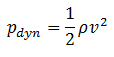
As can be seen, dynamic pressure is one of the terms of Bernoulli’s equation. In incompressible fluid dynamics, dynamic pressure is the quantity defined by:
The simplified form of Bernoulli’s equation can be summarized in the following memorable word equation:
static pressure + dynamic pressure = total pressure (stagnation pressure)
Total and dynamic pressure are not pressures in the usual sense – they cannot be measured using an aneroid, Bourdon tube, or mercury column.
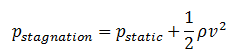
Many authors use the term static pressure to distinguish it from total pressure and dynamic pressure to avoid potential ambiguity when referring to pressure in fluid dynamics. The term static pressure is identical to the term pressure and can be identified for every point in a fluid flow field. Dynamic pressure is the difference between stagnation pressure and static pressure.
Stagnation pressure is equal to the sum of the free-stream dynamic pressure and free-stream static pressure.
Static pressure and dynamic pressure are terms of Bernoulli’s equation:
Bernoulli’s effect causes the lowering of fluid pressure (static pressure – p) in regions where the flow velocity is increased. This lowering of pressure in a constriction of a flow path may seem counterintuitive but seems less so when you consider the pressure to be energy density. In the high-velocity flow through the constriction, kinetic energy (dynamic pressure – ½.ρ.v2) must increase at the expense of pressure energy (static pressure – p).
The simplified form of Bernoulli’s equation can be summarized in the following memorable word equation:
static pressure + dynamic pressure = total pressure (stagnation pressure)
Total and dynamic pressure are not pressures in the usual sense – they cannot be measured using an aneroid, Bourdon tube, or mercury column.
Stagnation pressure is sometimes referred to as pitot pressure because it is measured using a pitot tube. A Pitot tube is a pressure measurement instrument used to measure fluid flow velocity. Velocity can be determined using the following formula:
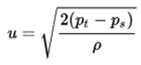
where:
- u is flow velocity to be measured in m/s,
- ps is stagnation or total pressure in Pa,
- pt is static pressure in Pa,
- ρ is fluid density in kg/m3.

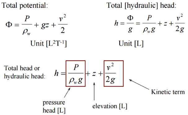
In fluid dynamics, the head is a concept that relates the energy in an incompressible fluid to the height of an equivalent static column of that fluid. The units for all the different forms of energy in Bernoulli’s equation can also be measured in distance units. Therefore these terms are sometimes referred to as “heads” (pressure head, velocity head, and elevation head). Head is also defined for pumps. This head is usually the static head and represents the maximum height (pressure) it can deliver. Therefore the characteristics of all pumps can usually be read from their Q-H curve (flow rate – height).
There are four types of potential (head):
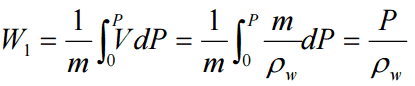
- Pressure potential – Pressure head: The pressure head represents the flow energy of a column of fluid whose weight is equivalent to the pressure of the fluid.
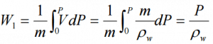 ρw: density of water assumed to be independent of pressure
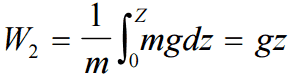
 - Elevation potential – Elevation head: The elevation head represents the potential energy of a fluid due to its elevation above a reference level.
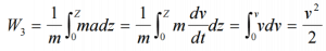
- Kinetic potential – Kinetic head: The kinetic head represents the kinetic energy of the fluid. The height in feet is that a flowing fluid would rise in a column if all of its kinetic energy were converted to potential energy.

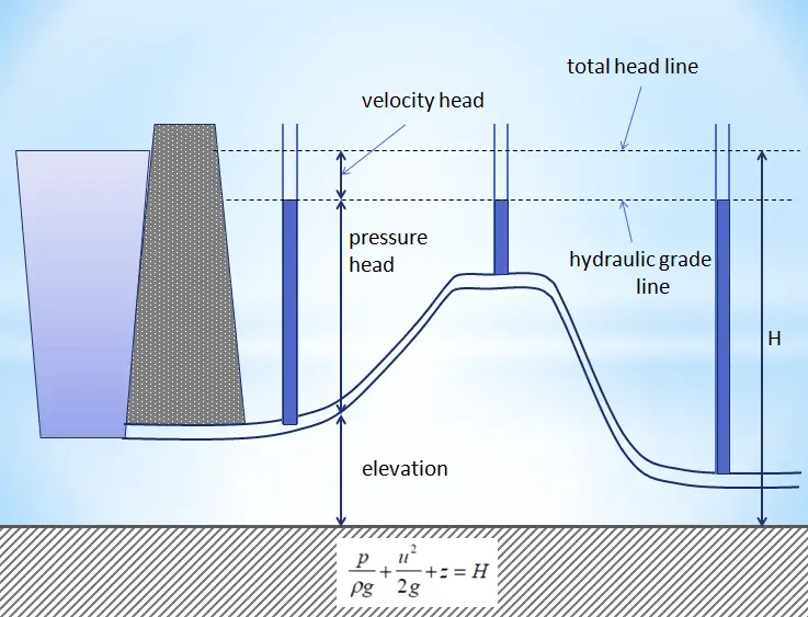
The sum of a fluid’s elevation head, kinetic head, and pressure head is called the total head. Thus, Bernoulli’s equation states that the total head of the fluid is constant.
Consider a pipe containing an ideal fluid. Suppose this pipe undergoes a gradual expansion in diameter. In that case, the continuity equation tells us that as the pipe diameter increases, the flow velocity must decrease to maintain the same mass flow rate. Since the outlet velocity is less than the inlet velocity, the kinetic head of the flow must decrease from the inlet to the outlet. If there is no change in the elevation head (the pipe lies horizontally), the decrease in the kinetic head must be compensated for by an increase in pressure head.
Example: Hydraulic Head

The exit is at standard atmospheric pressure (101 kPa) and is 200 m higher.
Calculate the frictional head loss Hf, and compare it to the flow v2/(2g) velocity head.
Solution:
Since the pipe diameter is constant, the average velocity and velocity head is the same everywhere:
vout = Q/A = 75 [m3/h] * 3600 [s/h] / 0.0113 [m2] = 1.84 m/s
Velocity head:
Velocity head = vout2/(2g) = 1.842 / 2*9.81 = 0.173 m
In order to find the frictional head loss, we have to use extended Bernoulli’s equation:
Head loss:
2 400 000 [Pa] / 1000 [kg/m3] * 9.81 [m/s2] + 0.173 [m] + 0 [m] = 101 000 [Pa] / 1000 [kg/m3] * 9.81 [m/s2] + 0.173 [m]+ 200 [m] + Hf
Hf = 244.6 – 10.3 – 200 = 34.3 m
Derivation of Bernoulli’s Equation
Conservation of Energy
This principle is generally known as the conservation of energy principle and states that the total energy of an isolated system remains constant — it is said to be conserved over time. This is equivalent to the First Law of Thermodynamics, which develops the general energy equation in thermodynamics. This principle can be used in the analysis of flowing fluids, and this principle is expressed mathematically by the following equation:
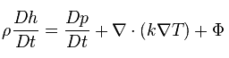 where h is enthalpy, k is the thermal conductivity of the fluid, T is temperature, and Φ is the viscous dissipation function.
Derivation
Bernoulli’s equation for incompressible fluids can be derived from Euler’s equations of motion under rather severe restrictions.
- The velocity must be derivable from a velocity potential.
- External forces must be conservative. That is, derivable from a potential.
- The density must either be constant or a function of the pressure alone.
- Thermal effects, such as natural convection, are ignored.
The Euler equations are a set of quasilinear hyperbolic equations governing adiabatic and inviscid flow in fluid dynamics. Euler equations can be obtained by linearization of these Navier–Stokes equations.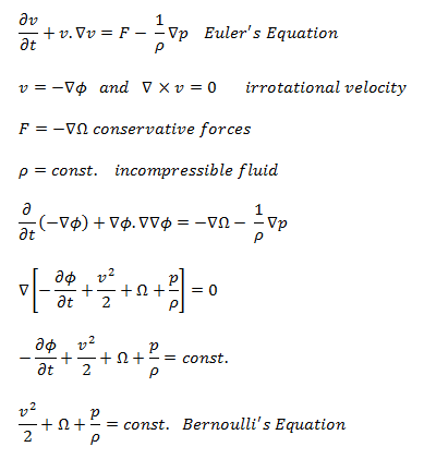
Extended Bernoulli’s Equation
Two main assumptions were applied to the derivation of the simplified Bernoulli equation.
- The first restriction on Bernoulli’s equation is that no work is allowed to be done on or by the fluid. This is a significant limitation because most hydraulic systems (especially in nuclear engineering) include pumps. This restriction prevents two points in a fluid stream from being analyzed if a pump exists between the two points.
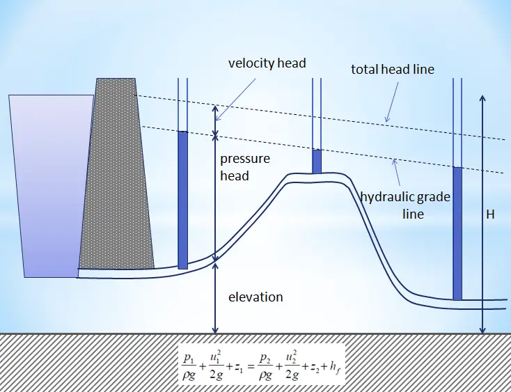
- The second restriction on simplified Bernoulli’s equation is that no fluid friction can solve hydraulic problems. In reality, friction plays a crucial role. The total head possessed by the fluid cannot be transferred completely and is lossless from one point to another. In reality, one purpose of pumps incorporated in a hydraulic system is to overcome the losses in pressure due to friction.
Due to these restrictions, most of the practical applications of the simplified Bernoulli equation to real hydraulic systems are very limited. The simplified Bernoulli equation must be modified to deal with both head losses and pump work.
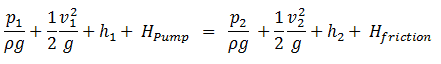
The Bernoulli equation can be modified to take into account gains and losses of the head. The resulting equation referred to as the extended Bernoulli’s equation is useful in solving most fluid flow problems. The following equation is one form of the extended Bernoulli equation.
where:
h = height above reference level (m)
v = average velocity of fluid (m/s)
p = pressure of fluid (Pa)
Hpump = head added by pump (m)
Hfriction = head loss due to fluid friction (m)
g = acceleration due to gravity (m/s2)
The head loss (or the pressure loss) due to fluid friction (Hfriction) represents the energy used in overcoming friction caused by the pipe walls. The head loss that occurs in pipes is dependent on the flow velocity, pipe diameter, and length, and a friction factor based on the roughness of the pipe and the Reynolds number of the flow. A piping system containing many pipe fittings and joints, tube convergence, divergence, turns, surface roughness, and other physical properties will also increase the head loss of a hydraulic system.
Although the head loss represents a loss of energy, it does not represent a loss of total energy of the fluid. The total energy of the fluid is conserved as a consequence of the law of conservation of energy. In reality, the head loss due to friction results in an equivalent increase in the fluid’s internal energy (temperature increases).
Most methods for evaluating head loss due to friction are based almost exclusively on experimental evidence. This will be discussed in the following sections.
Example – Relation between Pressure and Velocity
It is an illustrative example, and the following data do not correspond to any reactor design.
When Bernoulli’s equation is combined with the continuity equation, the two can find velocities and pressures at points in the flow connected by a streamline.
The continuity equation is simply a mathematical expression of the principle of conservation of mass. For a control volume with a single inlet and a single outlet, the principle of conservation of mass states that, for steady-state flow, the mass flow rate into the volume must equal the mass flow rate out.
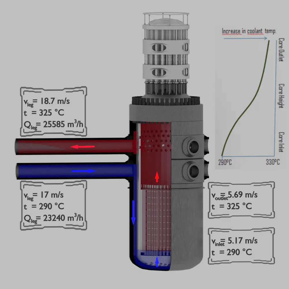
Example:
Determine pressure and velocity within a cold leg of primary piping and determine pressure and velocity at the bottom of a reactor core, about 5 meters below the cold leg of primary piping.
Let assume:
- The fluid of constant density ⍴ ~ 720 kg/m3 (at 290°C) flows steadily through the cold leg and the core bottom.
- Primary piping flow cross-section (single loop) is equal to 0.385 m2 (piping diameter ~ 700mm)
- Flow velocity in the cold leg is equal to 17 m/s.
- Reactor core flow cross-section is equal to 5m2.
- The gauge pressure inside the cold leg is equal to 16 MPa.
As a result of the Continuity principle the velocity at the bottom of the core is:
vinlet = vcold . Apiping / Acore = 17 x 1.52 / 5 = 5.17 m/s
As a result of Bernoulli’s principle, the pressure at the bottom of the core (core inlet) is:
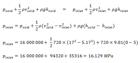
Bernoulli’s Principle – Lift Force
In general, the lift is an upward-acting force on an aircraft wing or airfoil. There are several ways to explain how an airfoil generates lift. Some theories are more complicated or more mathematically rigorous than others. Some theories are incorrect. There are theories based on Bernoulli’s principle, and theories are based directly on Newton’s third law.
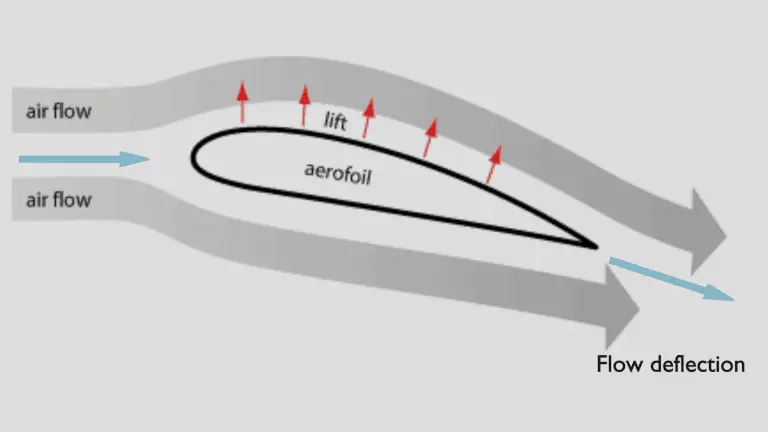
The explanation based on Newton’s third law states that the lift is caused by a flow deflection of the airstream behind the airfoil. The airfoil generates lift by exerting a downward force on the air as it flows past. According to Newton’s third law, the air must exert an upward force on the airfoil. This is a very simple explanation.
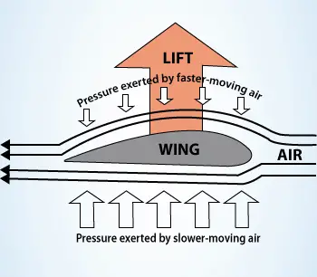
Bernoulli’s principle combined with the continuity equation can also be used to determine the lift force on an airfoil if the behavior of the fluid flow in the vicinity of the foil is known. In this explanation, the shape of an airfoil is crucial. The shape of an airfoil causes air to flow faster on top than on the bottom. According to Bernoulli’s principle, faster-moving air exerts less pressure, and therefore the air must exert an upward force on the airfoil (as a result of a pressure difference).
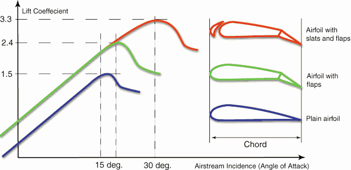
Bernoulli’s principle requires airfoil to be of an asymmetrical shape. Its surface area must be greater on the top than on the bottom. As the air flows over the airfoil, it is displaced more by the top surface than the bottom. According to the continuity principle, this displacement must increase flow velocity (resulting in a decrease in pressure). The flow velocity is increased by the bottom airfoil surface but considerably less than the flow on the top surface. The lift force of an airfoil, characterized by the lift coefficient, can be changed during the flight by changes in the shape of an airfoil. The lift coefficient can thus be even doubled with relatively simple devices (flaps and slats) if used on the full span of the wing.
The use of Bernoulli’s principle may not be correct. Bernoulli’s principle assumes incompressibility of the air, but in reality, the air is easily compressible. But there are more limitations of explanations based on Bernoulli’s principle. There are two main popular explanations of lift:
- Explanation based on downward deflection of the flow – Newton’s third law
- Explanation based on changes in flow speed and pressure – Continuity principle and Bernoulli’s principle
Both explanations correctly identify some aspects of the lift forces but leave other important aspects of the phenomenon unexplained. A more comprehensive explanation involves both changes in flow speed and downward deflection and requires looking at the flow in more detail.
See more: Doug McLean, Understanding Aerodynamics: Arguing from the Real Physics. John Wiley & Sons Ltd. 2013. ISBN: 978-1119967514
Bernoulli’s Effect – Spinning ball in an airflow
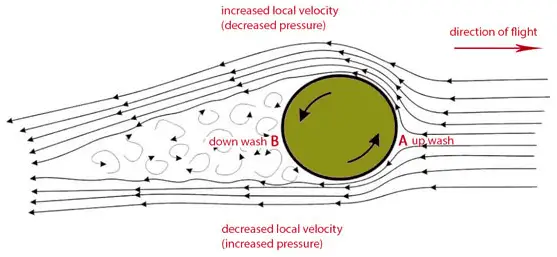 Bernoulli’s effect has another interesting consequence. Suppose a ball is spinning as it travels through the air. As the ball spins, the surface friction of the ball with the surrounding air drags a thin layer (referred to as the boundary layer) of air with it. It can be seen from the picture the boundary layer is on one side traveling in the same direction as the air stream that is flowing around the ball (the upper arrow). On the other side, the boundary layer travels in the opposite direction (the bottom arrow). On the side of the ball where the air stream and boundary layer are moving in the opposite direction (the bottom arrow) to each other, friction between the two slows the air stream. On the opposite side, these layers move in the same direction, and the stream moves faster.
According to Bernoulli’s principle, faster-moving air exerts less pressure, and therefore the air must exert an upward force on the ball. In fact, in this case, the use of Bernoulli’s principle may not be correct. Bernoulli’s principle assumes incompressibility of the air, but in reality, the air is easily compressible. But there are more limitations of explanations based on Bernoulli’s principle.
In Robert G. Watts and Ricardo Ferrer (The lateral forces on a spinning sphere: Aerodynamics of a curveball), this effect can be explained by another model, which gives important attention to the spinning boundary layer of air around the ball. The boundary layer tends to separate prematurely on the side of the ball, where the air stream and boundary layer are moving in the opposite direction (the bottom arrow). On the side of the ball, where the air stream and boundary layer are moving in the same direction, the boundary layer carries further around the ball before it separates into turbulent flow. This gives a flow deflection of the airstream in one direction behind the ball. The rotating ball generates lift by exerting a downward force on the air as it flows past. According to Newton’s third law, the air must exert an upward force on the ball.
Torricelli’s law
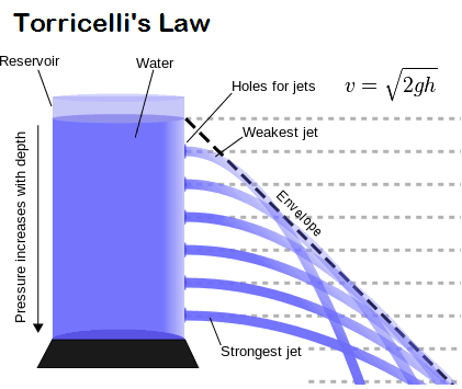
Torricelli’s law, also known as Torricelli’s principle, or Torricelli’s theorem, statement in fluid dynamics that the speed, v, of fluid flowing out of an orifice under the force of gravity in a tank is proportional to the square root of the vertical distance, h, between the liquid surface and the center of the orifice and to the square root of twice the acceleration caused by gravity (g = 9.81 N/kg near the surface of the earth).
In other words, the efflux velocity of the fluid from the orifice is the same as that it would have acquired by falling a height h under gravity. The law was discovered by and named after the Italian scientist Evangelista Torricelli in 1643. It was later shown to be a particular case of Bernoulli’s principle.
Torricelli’s equation is derived for a specific condition. The orifice must be small, and viscosity and other losses must be ignored. If a fluid is flowing through a very small orifice (for example, at the bottom of a large tank), then the velocity of the fluid at the large end can be neglected in Bernoulli’s Equation. Moreover, the speed of efflux is independent of the direction of flow. In that case, the efflux speed of fluid flowing through the orifice is given by the following formula:
v = √2gh