The steam condensers are broadly classified into two types:
- Surface condensers (or non-mixing type condensers). In surface condensers, there is no direct contact between the exhaust steam and the cooling water.
- Jet condensers (or mixing type condensers). In jet condensers, there is direct contact between the exhaust steam and cooling water.
Surface Condenser
The surface condenser is designed to condense and deaerate the exhaust steam from the main turbine and provide a heat sink for the turbine bypass system. In surface condensers, there is no direct contact between the exhaust steam and the cooling water. The exhausted steam from the LP turbines is condensed by passing over tubes containing water from the cooling system. The steam condenses when it comes in contact with the cold surface of the tubes and due to the heat transfer to cooling water by conduction and convection. These tubes are usually made of stainless steel, copper alloys, or titanium, depending on several selection criteria (such as thermal conductivity or corrosion resistance). Titanium condenser tubes are usually the best technical choice. However, titanium is a very expensive material, and titanium condenser tubes are associated with very high initial costs. In general, there are two types of surface condensers:
- water-cooled surface condenser
- air-cooled surface condenser
An air-cooled condenser can be used in thermal power plants, where cooling water is in short supply. However, an air-cooled condenser is significantly more expensive and cannot achieve as low a steam turbine exhaust pressure (and temperature) as a water-cooled surface condenser.
The water gets warmed in the condenser is discharged into the cooling system (i.e., cooling tower, river, sea, or cooling pond). The condensate collected from these condensers is reused as feedwater in the boiler. Since the cooling water and steam do not mix, the condensate is recovered, and any kind of cooling water can be used. In comparison to jet condensers, in surface condensers, a high vacuum can be maintained. We can achieve, therefore, greater thermal efficiency. On the other hand, surface condensers are bulky, require a large area, and have high capital costs. But these capital costs can be recovered by the improved thermal efficiency (i.e., higher )saving in running costs.
Thus, these condensers are most suitable for modern thermal power plants. These are generally used where a large quantity of inferior water is available, and better quality of feedwater is to be supplied to the boiler.
Jet Condenser
The cooling water is sprayed on the exhaust steam in jet condensers, and there is direct contact between the exhaust steam and cooling water. The condensation process is very fast and efficient, but cooling water and condensed steam are mixed up here. The condensate then cannot be reused as feedwater to the boilers. The temperature of the condensate is the same as that of the cooling water leaving the condenser. Due to the more intimate mixing of steam and cooling water, the jet condenser requires less quantity of cooling water for the condensation of steam. In general, jet condensers require less building space, and they are simpler in construction and lower in capital cost. Despite these advantages, jet condensers are not usual in thermal power plants, especially due to the loss of condensate.
Main Condenser
 The main steam condenser (MC) system is designed to condense and deaerate the exhaust steam from the main turbine and provide a heat sink for the turbine bypass system. In thermal power plants, there are usually surface condensers as the main condenser. The exhausted steam from the LP turbines is condensed by passing over tubes containing water from the cooling system. There is a main condenser unit under each LP turbine, usually below the turbine, with its axis perpendicular to the turbine axis. Since nuclear power plants usually contain also an auxiliary condenser (e.g., to condense steam from steam-driven feedwater pumps), engineers use the term “main condenser.”
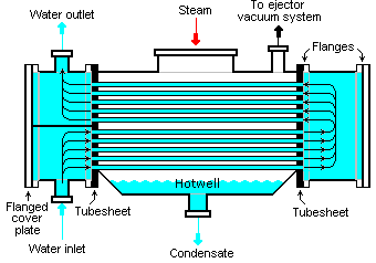
The pressure inside the condenser is given by the ambient air temperature (i.e., the temperature of water in the cooling system) and by steam ejectors or vacuum pumps, which pull the gases (non-condensable) from the surface condenser and eject them to the atmosphere. The pressure inside the condenser determines the overall power output of the power conversion system. Thermal power plants are usually equipped with so-called “surface condensers.”
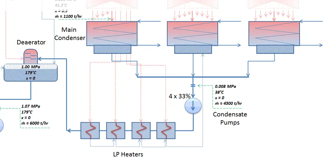
The condensed steam (now called condensate) is collected in the condenser’s hotwell. Condenser’s hotwell also provides a water storage capacity, which is required for operational purposes such as feedwater makeup. The condensate (saturated or slightly subcooled liquid) is delivered to the condensate pump and then pumped by condensate pumps to the deaerator through a feedwater heating system. The condensate pumps increase the pressure usually to about p = 1-2 MPa. There are usually four one-third-capacity centrifugal condensate pumps with common suction and discharge headers. Three pumps are normally in operation, with one in the backup.
Parameters of the Main Condenser
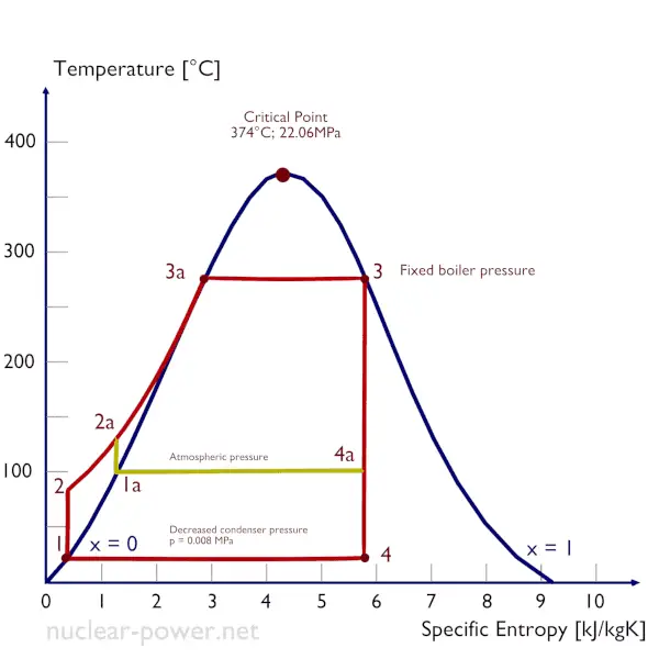
The condenser must maintain a sufficient low vacuum to increase the power plant efficiency. The vacuum pumps maintain a sufficient vacuum in the condenser by extracting air and uncondensed gases. The lowest feasible condenser pressure is the saturation pressure corresponding to the ambient temperature (e.g., the absolute pressure of 0.008 MPa, which corresponds to 41.5°C). Note that there is always a temperature difference between (around ΔT = 14°C) the condenser temperature and the ambient temperature, which originates from condensers’ finite size and efficiency. Since neither the condenser is a 100% efficient heat exchanger, there is always a temperature difference between the saturation temperature (secondary side) and the coolant temperature in the cooling system.
Moreover, there is design inefficiency, which decreases the overall efficiency of the turbine. Ideally, the steam exhausted into the condenser would have no subcooling. But real condensers are designed to subcool the liquid by a few degrees Celsius to avoid the suction cavitation in the condensate pumps. But, this subcooling increases the inefficiency of the cycle because more energy is needed to reheat the water.
The goal of maintaining the lowest practical turbine exhaust pressure is a primary reason for including the condenser in a thermal power plant. The condenser provides a vacuum that maximizes the energy extracted from the steam, resulting in a significant increase in net work and thermal efficiency. But also this parameter (condenser pressure) has its engineering limits:
- Decreasing the turbine exhaust pressure decreases the vapor quality (or dryness fraction). At some point, the expansion must be ended to avoid damages that could be caused to blades of steam turbine by low-quality steam.
- Decreasing the turbine exhaust pressure significantly increases the specific volume of exhausted steam, which requires huge blades in the last rows of a low-pressure stage of the steam turbine.
In a typical wet steam turbine, the exhausted steam condenses in the condenser, and it is at a pressure well below atmospheric (absolute pressure of 0.008 MPa, which corresponds to 41.5°C). This steam is in a partially condensed state (point F), typically of a quality near 90%. Note that the pressure inside the condenser is also dependent on the ambient atmospheric conditions:
- air temperature, pressure, and humidity in case of cooling into the atmosphere
- water temperature and the flow rate in case of cooling into a river or sea
An increase in the ambient temperature causes a proportional increase in pressure of exhausted steam (ΔT = 14°C is usually a constant); hence the thermal efficiency of the power conversion system decreases. In other words, the electrical output of a power plant may vary with ambient conditions, while the thermal power remains constant.
To maintain the parameters inside the condenser (0.008 MPa and 41.5 °C), the cooling water from the cooling system must be sufficiently cold, and there cannot be a large temperature difference between the outlet and inlet water temperature; hence the flow rate through the cooling system must be very high. The flow rate through the cooling system (with wet cooling towers) may be up to 100 000 m3/h (27.7 m3/s). The condenser inlet water may have about 22°C (strongly depending on ambient conditions), while the condenser outlet may have about 25°C. The seawater cooling systems operate at higher flow rates, for example, 130 000 m3/h.