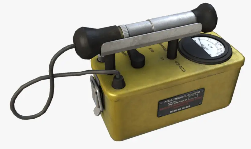
Gaseous ionization detectors are radiation detection instruments used in radiation protection applications to measure ionizing radiation and particle physics to detect the presence of ionizing particles. These detectors are designed to measure the ionization produced when an incident particle traverses some medium and are based on radiation’s ionizing effect. For ionizing radiation to occur, the kinetic energy of particles (photons, electrons, etc.) of ionizing radiation is sufficient. The particle can ionize (to form ions by losing electrons) target atoms to form ions. Simply ionizing radiation can knock electrons from an atom.
The basic gaseous ionization detector consists of a chamber filled with a suitable medium (air or a special fill gas) that can be easily ionized. The most widely used types of these detectors are based on the effects produced when a charged particle passes through a gas. The operating medium:
- should be chemically stable (or inert) so that the moving ionization electrons are not easily captured by the molecules of that medium
- should have a low ionization potential (I) value to maximize the amount of ionization produced per energy deposited by any incident particle.
- should not be very sensitive to radiation damage so that its response to incident particles does not change markedly with use.
Typical gases used in detectors are argon and helium, although boron-trifluoride (BF3) is utilized when the detector is to be used to measure neutrons. Gaseous ionization detectors are widely used in nuclear power plants, for the most part, to measure alpha and beta particles, neutrons, and gamma rays. The detectors operate in the ionization, proportional, and Geiger-Mueller regions, with an arrangement most sensitive to the measured radiation type. Neutron detectors utilize ionization chambers or proportional counters of appropriate design. Compensated ion chambers, BF3 counters, fission counters, and proton recoil counters are examples of neutron detectors.
Basic Principle of Gaseous Ionization Detectors
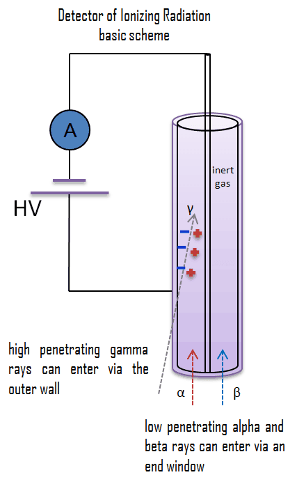
The chamber has a cathode and an anode that are held at some large relative voltage, and the device is characterized by a capacitance determined by the geometry of the electrodes. As ionizing radiation enters the gas between the electrodes, a finite number of ion pairs are formed. The behavior of the resultant ion pairs is affected by the potential gradient of the gas’s electric field and the fill gas’s type and pressure. Under the influence of the electric field, the positive ions will move toward the negatively charged electrode (outer cylinder), and the negative ions (electrons) will migrate toward the positive electrode (central wire). The electric field in this region keeps the ions from recombining with the electrons. Collecting these ions will produce a charge on the electrodes and an electrical pulse across the detection circuit. The average energy needed to produce an ion in the air is about 34 eV. Therefore a 1 MeV radiation completely absorbed in the detector produces about 3 x 10⁴ pairs of ions. However, it is a small signal that can be considerably amplified using standard electronics.
Operating Regions of Ionizing Detectors – Detector Voltage
The relationship between the applied voltage and pulse height in a detector is very complex. Pulse height and the number of ion pairs collected are directly related. As was written, voltages can vary widely depending upon the detector geometry, gas type, and pressure. The figure schematically indicates the different voltage regions for alpha, beta, and gamma rays. There are six main practical operating regions, where three (ionization, proportional, and Geiger-Mueller region) are useful for detecting ionizing radiation. These regions are shown below. The alpha curve is higher than the beta and gamma curve from the recombination region to part of the limited proportionality region due to the larger number of ion pairs produced by the initial reaction of the incident radiation.
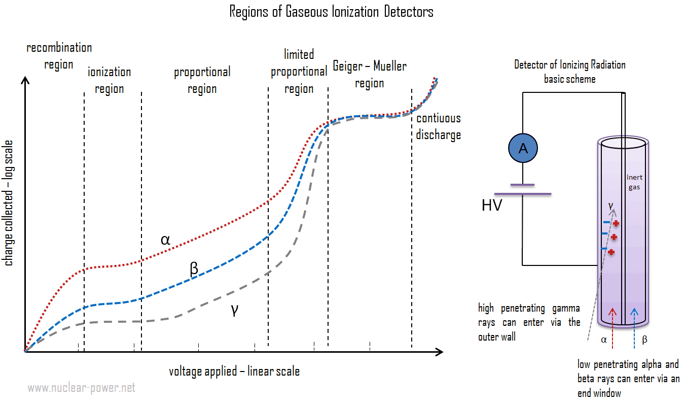
- Recombination Region. The electric field is not large enough at low voltage to accelerate electrons and ions. The electrons and ions can recombine soon after they are produced, and only a small fraction of the produced electrons and ions reach their respective electrodes. As the detector voltage increases, however, an increasingly large fraction of the ions produced will reach the electrodes. This increase continues until the “saturation” voltage is attained. The operating voltage range where this occurs is referred to as the recombination region. Detectors are not operated in this region because neither the number of recombinations nor the number of ion pairs initially produced can be determined accurately.
- Ionization Region. In the ionization region, an increase in voltage does not cause a substantial increase in the number of ion pairs collected. The number of ion pairs collected by the electrodes equals the number of ion pairs produced by the incident radiation. It is dependent on the type and energy of the particles or rays in the incident radiation. Therefore, in this region, the curve is flat. The voltage must be higher than the point where dissociated ion pairs can recombine. On the other hand, the voltage is not high enough to produce gas amplification (secondary ionization). Detectors in the ionization region operate at a low electric field strength, selected so that no gas multiplication occurs, and their current is independent of the applied voltage. They are preferred for high radiation dose rates because they have no “dead time,” a phenomenon that affects the accuracy of the Geiger-Mueller tube at high dose rates.
- Proportional Region. In the proportional region, the charge collected increases with a further increase in the detector voltage, while the number of primary ion pairs remains unchanged. Increasing the voltage provides the primary electrons with sufficient acceleration and energy to ionize additional atoms of the medium. These secondary ions formed are also accelerated, causing an effect known as Townsend avalanches, which creates a single large electrical pulse. Even though there is a large number of secondary ions (about 103 – 105) for each primary event, the chamber is always operated such that the number of secondary ions is proportional to the number of primary events. It is very important because the primary ionization is dependent on the type and energy of the particles or rays in the intercepted radiation field. The number of ion pairs collected divided by the number of ion pairs produced by the primary ionization provides the gas amplification factor (denoted by A). The gas amplification in this region can increase the total amount of ionization to a measurable value. The charge amplification process greatly improves the detector’s signal-to-noise ratio and reduces the subsequent electronic amplification required. The voltage must be kept constant when instruments are operated in the proportional region. If a voltage remains constant, the gas amplification factor also does not change. Proportional counter detection instruments are very sensitive to low levels of radiation. Moreover, proportional counters are capable of particle identification and energy measurement (spectroscopy). Different energies of radiation and different types of radiation can be distinguished by analyzing the pulse height since they significantly differ in the primary ionization.
- Limited Proportional Region. In the limited proportional region, the gas amplification factor does not continue to increase proportionally to the voltage. Additional ionizations and nonlinear effects cause no proportionality of the output signal to the deposited energy at a given applied voltage. The electric field in the chamber is distorted due to the high positive ion concentration. Free electrons are much lighter than the positive ions; thus, they are drawn toward the positive central electrode much faster than the positive ions are drawn to the chamber wall. The resulting cloud of positive ions near the electrode leads to distortions in gas multiplication. This region is usually avoided as a detection region.
- Geiger-Mueller Region. In the Geiger-Mueller region, the voltage and thus the electric field are so strong that secondary avalanches can occur. These avalanches can be triggered and propagated by photons emitted by atoms excited in the original avalanche. Since these photons are not affected by the electric field, they may interact far (e.g., laterally to the axis) from the primary avalanche. The entire Geiger tube is participating in the process. A strong signal (the amplification factor can reach about 1010) is produced by these avalanches with shape and height independently of the primary ionization and the energy of the detected photon. Detectors operated in the Geiger-Mueller region can detect gamma rays and all types of charged particles that can enter the detector. These detectors are known as Geiger counters. The main advantage of these instruments is that they usually do not require any signal amplifiers. Since the positive ions do not move far from the avalanche region, a positively charged ion cloud disturbs the electric field and terminates the avalanche process. In practice, the termination of the avalanche is improved by the use of “quenching” techniques. In contrast to proportional counters, the energy of incident radiation particles can not be distinguished by Geiger counters since the output signal is independent of the amount and type of original ionization.
- Discharge Region. Finally, at still higher voltages (above the Geiger-Mueller region), the electric field generates a continuous discharge of the medium, with the chamber no longer being sensitive to any incident ionization. This region is not used for the detection or measurement of ionizing radiation. Suppose the Geiger tube voltage is increased above the end of the plateau. In that case, the count rate increases rapidly until the onset of continuous discharge, where the tube cannot detect radiation and may be damaged.
Types of Detectors of Ionizing Radiation
As a result, there are three basic types of gaseous ionization detectors, which are categorized according to the voltage applied to the detector:
- ionization chambers,
- proportional counters,
- Geiger-Müller tubes.
As with other detectors, ionization chambers can be operated in current or pulse mode. In contrast, pulse mode almost always uses proportional counters or Geiger counters. Detectors of ionizing radiation can be used both for activity measurements as well as for dose measurements. The dose can be obtained with knowledge about the energy needed to form a pair of ions.